752161473GPTR CTS Resistor Products, 752161473GPTR Datasheet - Page 4
752161473GPTR
Manufacturer Part Number
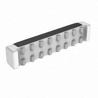
752161473GPTR
Description
RES-NET 47K OHM BUSSED SMD
Manufacturer
CTS Resistor Products
Series
752r
Specifications of 752161473GPTR
Resistance (ohms)
47K
Number Of Resistors
14
Circuit Type
Bussed
Temperature Coefficient
±200ppm/°C
Tolerance
±2%
Power Per Element
80mW
Number Of Pins
16
Package / Case
16-DRT
Size / Dimension
0.465" L x 0.080" W (11.81mm x 2.03mm)
Height
0.095" (2.41mm)
Mounting Type
Surface Mount
Operating Temperature
-55°C ~ 125°C
Lead Free Status / RoHS Status
Lead free / RoHS Compliant
Other names
752-161-47KPTR


www.national.com
V
FB
Electrical Characteristics V
The following specifications apply for V
wise specified. Limits apply for T
Note 1: All voltages are measured with respect to the GND pin, unless otherwise specified.
Note 2: Absolute Maximum Ratings indicate limits beyond which damage to the device may occur. Operating Ratings indicate conditions for which the device is
functional, but do not guarantee specific performance limits. Electrical Characteristics state DC and AC electrical specifications under particular test conditions which
guarantee specific performance limits. This assumes that the device is within the Operating Ratings. Specifications are not guaranteed for parameters where no limit
is given, however, the typical value is a good indication of device performance.
Note 3: The maximum power dissipation must be derated at elevated temperatures and is dictated by T
allowable power dissipation is P
Note 4: Human body model, 100pF discharged through a 1.5kΩ resistor.
Note 5: Machine Model, 220pF–240pF discharged through all pins.
Note 6: Typicals are measured at 25˚C and represent the parametric norm.
Note 7: Limits are guaranteed to National’s AOQL (Average Outgoing Quality Level).
Note 8: Datasheet min/max specification limits are guaranteed by design, test, or statistical analysis.
Note 9: Shutdown current is measured at an ambient temperature of 25˚C. The Shutdown pin should be driven as close as possible to GND for minimum shutdown
current.
Note 10: Shutdown current is measured with components R1 and R2 removed.
Note 11: Feedback pin reference voltage is measured with the Audio Amplifier’s V1 (pin 26) floating and no addition load connected to the cathode of D1 (see Figure
1).
Symbol
Feedback Pin Reference Voltage
DMAX
Parameter
= (T
A
JMAX
= 25˚C.
− T
DD
A
) / θ
= 3.0V, A
JA
DD
or the given in Absolute Maximum Ratings, whichever is lower.
= 3.0V
V-BTL
(Note 11)
= 26dB, R
(Notes 1, 2) (Continued)
4
Conditions
L
= 8Ω, C
B
= 1.0µF, R
JMAX
, θ
JA
, and the ambient temperature, T
1
= 51.1kΩ, R
(Note 6)
Typical
1.23
LM4805
2
(Notes 7, 8)
= 15kΩ unless other-
1.205
1.255
Limit
A
. The maximum
(Limits)
V (max)
V (min)
Units
Related parts for 752161473GPTR
Image
Part Number
Description
Manufacturer
Datasheet
Request
R

Part Number:
Description:
RESISTOR NET 4.7K OHM SMD
Manufacturer:
CTS Resistor Products
Datasheet:

Part Number:
Description:
RES .10 OHM 1/8W 5% 0805
Manufacturer:
CTS Resistor Products
Datasheet:

Part Number:
Description:
RES .20 OHM 1/10W 5% 0402
Manufacturer:
CTS Resistor Products
Datasheet:

Part Number:
Description:
RES .47 OHM 1/8W 5% 0805
Manufacturer:
CTS Resistor Products
Datasheet:

Part Number:
Description:
RES .47 OHM 1/10W 5% 0402
Manufacturer:
CTS Resistor Products
Datasheet:

Part Number:
Description:
RES .47 OHM 1/4W 5% 1206
Manufacturer:
CTS Resistor Products
Datasheet:

Part Number:
Description:
RES .20 OHM 1/10W 5% 0603
Manufacturer:
CTS Resistor Products
Datasheet:

Part Number:
Description:
RES .47 OHM 1/2W 5% 1210
Manufacturer:
CTS Resistor Products
Datasheet:

Part Number:
Description:
RES .20 OHM 1/2W 5% 1210
Manufacturer:
CTS Resistor Products
Datasheet:

Part Number:
Description:
RES .47 OHM .75W 5% 2010
Manufacturer:
CTS Resistor Products
Datasheet:

Part Number:
Description:
RES .20 OHM .75W 5% 2010
Manufacturer:
CTS Resistor Products
Datasheet:

Part Number:
Description:
RES .56 OHM .75W 5% 2010
Manufacturer:
CTS Resistor Products
Datasheet:

Part Number:
Description:
RES .91 OHM .75W 5% 2010
Manufacturer:
CTS Resistor Products
Datasheet:

Part Number:
Description:
RES .050 OHM .5W 5% 1206
Manufacturer:
CTS Resistor Products
Datasheet:

Part Number:
Description:
RES NET 15RES 4.7K OHM 16PIN SMD
Manufacturer:
CTS Resistor Products
Datasheet: