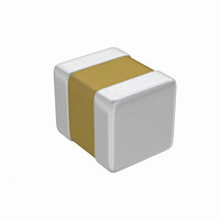
05045C103MA79A AVX Corporation, 05045C103MA79A Datasheet - Page 39

05045C103MA79A
Manufacturer Part Number
05045C103MA79A
Description
CAP CER 10000PF 50V X7R 0504
Manufacturer
AVX Corporation
Datasheet
1.05041A1R0DAT1A.pdf
(48 pages)
Specifications of 05045C103MA79A
Capacitance
10000pF
Voltage - Rated
50V
Tolerance
±20%
Temperature Coefficient
X7R
Mounting Type
Surface Mount, MLCC
Operating Temperature
-55°C ~ 125°C
Features
Low ESL
Applications
General Purpose
Package / Case
0504 (1210 Metric)
Size / Dimension
0.050" L x 0.040" W (1.27mm x 1.02mm)
Thickness
1.02mm Max
Lead Free Status / RoHS Status
Lead free / RoHS Compliant
Ratings
-
Lead Spacing
-
Embossed Carrier Configuration
8 & 12 mm Tape Only
8 & 12 mm Embossed Tape
Metric Dimensions Will Govern
CONSTANT DIMENSIONS
VARIABLE DIMENSIONS
NOTES:
1. A
2. Tape with components shall pass around radius “R” without damage. The minimum trailer length (Note 2 Fig. 3) may require additional length to provide R min. for 12 mm
3. G
4. G
5. The embossment hole location shall be measured from the sprocket hole controlling the location of the emboss-
6. B
Tape Size
Tape Size
1/2 Pitch
clearance between the end of the terminals or body of the component to the sides and depth of the cavity (A
(.020) max. The clearance allowed must also prevent rotation of the component within the cavity of not more than 20 degrees (see sketches C & D).
embossed tape for reels with hub diameters approaching N min. (Table 4).
ty whichever is less.
to the edge of the cavity whichever is less.
ment. Dimensions of embossment location and hole location shall be applied independent of each other.
0
1
1
2
Double
, B
12mm
12mm
12mm
dimension is a reference dimension for tape feeder clearance only.
dimension is the flat area from the edge of the sprocket hole to either the outward deformation of the carrier tape between the embossed cavities or to the edge of the cavi-
dimension is the flat area from the edge of the carrier tape opposite the sprocket holes to either the outward deformation of the carrier tape between the embossed cavity or
8mm
8mm
8mm
Pitch
and
0
, and K
0
are determined by the max. dimensions to the ends of the terminals extending from the component body and/or the body dimensions of the component. The
See Note 6 See Note 5
(.059
8.4
(.179)
(.323)
(.179)
(.323)
Max.
4.55
4.55
8.2
8.2
D
B
+0.10
-0.0
0
1
+.004
-0.0
)
(.069 ± .004) (.157 ± .004) (.079 ± .002)
1.75 ± 0.10
(.039)
(.059)
(.059)
(.039)
Min.
1.0
1.5
1.0
1.5
D
E
1
(.138 ± .002) (.157 ± .004)
(.217 ± .002) (.157 ± .004)
(.138 ± .002) 0.79 ± .004
(.217 ± .002) (.315 ± .004)
4.0 ± 0.10
3.5 ± 0.05
5.5 ± 0.05
3.5 ± 0.05
5.5 ± 0.05
P
F
0
4.0 ± 0.10
4.0 ± 0.10
2.0 ± 0.10
8.0 ± 0.10
2.0 ± 0.05
P
P
2
1
See Note 2
T Max.
(1.181)
(1.181)
0.600
(.024)
(.984)
(.984)
Min.
25
30
25
30
R
0
, B
0
, and K
6.5 Max.
2.5 Max.
6.5 Max.
2.5 Max
(.004)
(.098)
(.256)
(.098)
(.256)
Max.
0.10
0
) must be within 0.05 mm (.002) min. and 0.50 mm
T
T
1
2
(.472 ± .012)
(.472 ± .012)
See Note 3
12.0 ± .30
12.0 ± .30
(.315
(.315
(.030)
0.75
8.0
Min.
8.0
G
W
1
+0.3
+0.3
-0.1
-0.1
+.012
+.012
-.004
-.004
)
)
See Note 4
See Note 1
See Note 1
See Note 1
See Note 1
A
(.030)
0
0.75
Min.
G
B
2
0
K
0
37


