ST10F269Z2Q3 STMicroelectronics, ST10F269Z2Q3 Datasheet - Page 148

ST10F269Z2Q3
Manufacturer Part Number
ST10F269Z2Q3
Description
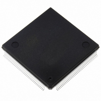
IC FLASH MEM 256KBIT 144-PQFP
Manufacturer
STMicroelectronics
Series
ST10r
Datasheet
1.ST10F269Z2Q3.pdf
(184 pages)
Specifications of ST10F269Z2Q3
Core Processor
ST10
Core Size
16-Bit
Speed
40MHz
Connectivity
CAN, EBI/EMI, SSC, UART/USART
Peripherals
POR, PWM, WDT
Number Of I /o
111
Program Memory Size
256KB (256K x 8)
Program Memory Type
FLASH
Ram Size
12K x 8
Voltage - Supply (vcc/vdd)
4.5 V ~ 5.5 V
Data Converters
A/D 16x10b
Oscillator Type
Internal
Operating Temperature
-40°C ~ 125°C
Package / Case
144-QFP
Processor Series
ST10F26x
Core
ST10
Data Bus Width
16 bit
Data Ram Size
12 KB
Interface Type
CAN, SSC, USART
Maximum Clock Frequency
40 MHz
Number Of Programmable I/os
111
Number Of Timers
2 x 16 bit
Operating Supply Voltage
0.3 V to 4 V
Maximum Operating Temperature
+ 125 C
Mounting Style
SMD/SMT
Minimum Operating Temperature
- 40 C
On-chip Adc
16 bit x 10 bit
Cpu Family
ST10
Device Core Size
16b
Frequency (max)
40MHz
Total Internal Ram Size
12KB
# I/os (max)
111
Number Of Timers - General Purpose
5
Operating Supply Voltage (typ)
5V
Operating Supply Voltage (max)
5.5V
Operating Supply Voltage (min)
4.5V
Instruction Set Architecture
CISC/RISC
Operating Temp Range
-40C to 125C
Operating Temperature Classification
Automotive
Mounting
Surface Mount
Pin Count
144
Package Type
PQFP
Lead Free Status / RoHS Status
Lead free / RoHS Compliant
Eeprom Size
-
Lead Free Status / Rohs Status
Lead free / RoHS Compliant
Other names
497-2042
Available stocks
Company
Part Number
Manufacturer
Quantity
Price
Company:
Part Number:
ST10F269Z2Q3
Manufacturer:
INFINEON
Quantity:
1 443
Company:
Part Number:
ST10F269Z2Q3
Manufacturer:
STMicroelectronics
Quantity:
10 000
Part Number:
ST10F269Z2Q3
Manufacturer:
ST
Quantity:
20 000
21.4.3 - Clock Generation Modes
The Table 44 associates the combinations of these three bits with the respective clock generation mode.
Table 44 : CPU Frequency Generation (PQFP144 devices)
Notes: 1. The external clock input range refers to a CPU clock range of 1...40MHz.
.
Table 45 : CPU Frequency Generation (TQFP144 devices)
Notes: 1. The external clock input range refers to a CPU clock range of 1...32MHz.
148/184
P0H.7 P0H.6 P0H.5 CPU Frequency f
P0H.7 P0H.6 P0H.5 CPU Frequency f
1
1
1
1
0
0
0
0
1
1
1
1
0
0
0
0
2. The maximum input frequency depends on the duty cycle of the external clock signal.
3. The maximum input frequency is 25MHz when using an external crystal with the internal oscillator; providing that internal serial
resistance of the crystal is less than 40 . However, higher frequencies can be applied with an external clock source on pin XTAL1,
but in this case, the input clock signal must reach the defined levels V
2. The maximum input frequency depends on the duty cycle of the external clock signal.
3. The maximum input frequency is 32MHz when using an external crystal with the internal oscillator; providing that internal serial
resistance of the crystal is less than 40 . However, higher frequencies can be applied with an external clock source on pin XTAL1,
but in this case, the input clock signal must reach the defined levels V
1
1
0
0
1
1
0
0
1
1
0
0
1
1
0
0
1
0
1
0
1
0
1
0
1
0
1
0
1
0
1
0
f
f
f
f
f
f
XTAL
XTAL
XTAL
XTAL
XTAL
XTAL
f
f
f
f
f
f
f
f
f
f
XTAL
XTAL
XTAL
XTAL
XTAL
XTAL
XTAL
XTAL
XTAL
XTAL
x 1.5
x 0.5
x 2.5
x 1.5
x 0.5
x 2.5
x 4
x 3
x 2
x 5
x 1
x 4
x 3
x 2
x 5
x 1
CPU
CPU
= f
= f
XTAL
XTAL
x F External Clock Input Range
x F External Clock Input Range
IL
IL
3.33 to 13.33MHz
6.66 to 26.66MHz
3.33 to 10.67MHz
6.67 to 21.33MHz
and V
and V
2.5 to 10MHz
4 to 12.8MHz
2.5 to 8MHz
2 to 6.4MHz
5 to 20MHz
1 to 40MHz
2 to 80MHz
4 to 16MHz
5 to 16MHz
1 to 32MHz
2 to 64MHz
2 to 8MHz
IH2.
IH2.
.
.
1
1
Default configuration
Direct drive
CPU clock via prescaler
Default configuration
Direct drive
CPU clock via prescaler
Notes
Notes
2
2
ST10F269
3
3


