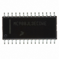
MC908JL3ECDWE Freescale Semiconductor, MC908JL3ECDWE Datasheet - Page 57

MC908JL3ECDWE
Manufacturer Part Number
MC908JL3ECDWE
Description
IC MCU 4K FLASH 8MHZ 28-SOIC
Manufacturer
Freescale Semiconductor
Series
HC08r
Datasheet
1.MC908JK1ECDWE.pdf
(180 pages)
Specifications of MC908JL3ECDWE
Core Processor
HC08
Core Size
8-Bit
Speed
8MHz
Peripherals
LED, LVD, POR, PWM
Number Of I /o
23
Program Memory Size
4KB (4K x 8)
Program Memory Type
FLASH
Ram Size
128 x 8
Voltage - Supply (vcc/vdd)
2.7 V ~ 3.3 V
Data Converters
A/D 12x8b
Oscillator Type
External
Operating Temperature
-40°C ~ 85°C
Package / Case
28-SOIC (7.5mm Width)
Processor Series
HC08JL
Core
HC08
Data Bus Width
8 bit
Data Ram Size
128 B
Maximum Clock Frequency
8 MHz
Number Of Programmable I/os
26
Number Of Timers
2
Operating Supply Voltage
3 V to 5 V
Maximum Operating Temperature
+ 85 C
Mounting Style
SMD/SMT
Development Tools By Supplier
FSICEBASE, DEMO908JL16E, M68CBL05CE
Minimum Operating Temperature
- 40 C
On-chip Adc
8 bit, 12 Channel
Lead Free Status / RoHS Status
Lead free / RoHS Compliant
Eeprom Size
-
Connectivity
-
Lead Free Status / Rohs Status
Details
Available stocks
Company
Part Number
Manufacturer
Quantity
Price
Company:
Part Number:
MC908JL3ECDWE
Manufacturer:
FREE
Quantity:
118
Company:
Part Number:
MC908JL3ECDWE
Manufacturer:
FREESCAL
Quantity:
68
Part Number:
MC908JL3ECDWE
Manufacturer:
FREESCALE
Quantity:
20 000
At the beginning of an interrupt, the CPU saves the CPU register contents on the stack and sets the
interrupt mask (I bit) to prevent additional interrupts. At the end of an interrupt, the RTI instruction recovers
the CPU register contents from the stack so that normal processing can resume.
interrupt entry timing.
5.5.1.1 Hardware Interrupts
A hardware interrupt does not stop the current instruction. Processing of a hardware interrupt begins after
completion of the current instruction. When the current instruction is complete, the SIM checks all pending
hardware interrupts. If interrupts are not masked (I bit clear in the condition code register), and if the
corresponding interrupt enable bit is set, the SIM proceeds with interrupt processing; otherwise, the next
instruction is fetched and executed.
If more than one interrupt is pending at the end of an instruction execution, the highest priority interrupt is
serviced first.
pending upon exit from the original interrupt service routine, the pending interrupt is serviced before the
LDA instruction is executed.
Freescale Semiconductor
INTERRUPT
INTERRUPT
MODULE
MODULE
I BIT
I BIT
R/W
R/W
IDB
IDB
IAB
IAB
Figure 5-11
DUMMY
Figure 5-10
DUMMY
demonstrates what happens when two interrupts are pending. If an interrupt is
SP – 4
SP
PC – 1[7:0] PC – 1[15:8]
CCR
MC68HC908JL3E Family Data Sheet, Rev. 4
Figure 5-10. Interrupt Recovery
shows interrupt recovery timing.
SP – 1
SP – 3
Figure 5-9
A
SP – 2
SP – 2
.
X
Interrupt Entry
X
SP – 3
SP – 1
PC – 1[15:8] PC – 1[7:0] OPCODE
A
SP – 4
SP
CCR
VECT H
PC
V DATA H
VECT L
PC + 1
V DATA L
OPERAND
Figure 5-9
START ADDR
Exception Control
OPCODE
shows
57


