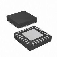
ATTINY48-MMU Atmel, ATTINY48-MMU Datasheet - Page 297

ATTINY48-MMU
Manufacturer Part Number
ATTINY48-MMU
Description
MCU AVR 5K FLASH 12MHZ 28-QFN
Manufacturer
Atmel
Series
AVR® ATtinyr
Specifications of ATTINY48-MMU
Core Processor
AVR
Core Size
8-Bit
Speed
12MHz
Connectivity
I²C, SPI
Peripherals
Brown-out Detect/Reset, POR, WDT
Number Of I /o
24
Program Memory Size
4KB (2K x 16)
Program Memory Type
FLASH
Eeprom Size
64 x 8
Ram Size
256 x 8
Voltage - Supply (vcc/vdd)
1.8 V ~ 5.5 V
Data Converters
A/D 6x10b
Oscillator Type
Internal
Operating Temperature
-40°C ~ 85°C
Package / Case
28-VQFN Exposed Pad, 28-HVQFN, 28-SQFN, 28-DHVQFN
Processor Series
ATTINY4x
Core
AVR8
Data Bus Width
8 bit
Data Ram Size
256 B
Interface Type
2-Wire, I2S, SPI
Maximum Clock Frequency
12 MHz
Number Of Programmable I/os
24
Number Of Timers
2
Maximum Operating Temperature
+ 85 C
Mounting Style
SMD/SMT
3rd Party Development Tools
EWAVR, EWAVR-BL
Development Tools By Supplier
ATAVRDRAGON, ATSTK500, ATSTK600, ATAVRISP2, ATAVRONEKIT
Minimum Operating Temperature
- 40 C
On-chip Adc
10 bit, 6 Channel
Package
28VQFN EP
Device Core
AVR
Family Name
ATtiny
Maximum Speed
12 MHz
Operating Supply Voltage
2.5|3.3|5 V
For Use With
ATAVRDRAGON - KIT DRAGON 32KB FLASH MEM AVR
Lead Free Status / RoHS Status
Lead free / RoHS Compliant
- Current page: 297 of 302
- Download datasheet (9Mb)
8008G–AVR–04/11
13 Timer/Counter0 and Timer/Counter1 Prescalers .............................. 117
14 SPI – Serial Peripheral Interface ......................................................... 120
15 TWI – Two Wire Interface .................................................................... 129
16 Analog Comparator ............................................................................. 161
12.3
12.4
12.5
12.6
12.7
12.8
12.9
12.10
12.11
13.1
13.2
13.3
13.4
14.1
14.2
14.3
14.4
14.5
15.1
15.2
15.3
15.4
15.5
15.6
15.7
15.8
15.9
15.10
15.11
16.1
16.2
Accessing 16-bit Registers ..............................................................................91
Timer/Counter Clock Sources .........................................................................93
Counter Unit ....................................................................................................94
Input Capture Unit ...........................................................................................95
Output Compare Units .....................................................................................97
Compare Match Output Unit ............................................................................99
Modes of Operation .......................................................................................100
Timer/Counter Timing Diagrams ...................................................................107
Register Description ......................................................................................110
Internal Clock Source ....................................................................................117
Prescaler Reset .............................................................................................117
External Clock Source ...................................................................................117
Register Description ......................................................................................118
Features ........................................................................................................120
Overview ........................................................................................................120
SS Pin Functionality ......................................................................................124
Data Modes ...................................................................................................125
Register Description ......................................................................................126
Features ........................................................................................................129
Overview ........................................................................................................129
Bus Definitions ...............................................................................................129
Data Transfer and Frame Format ..................................................................130
Multi-master Bus Systems, Arbitration and Synchronization .........................133
Overview of the TWI Module .........................................................................135
Using the TWI ................................................................................................137
Transmission Modes .....................................................................................140
Multi-master Systems and Arbitration ............................................................154
Compatibility with SMBus ..............................................................................156
Register Description ......................................................................................156
Analog Comparator Multiplexed Input ...........................................................161
Register Description ......................................................................................162
ATtiny48/88
iii
Related parts for ATTINY48-MMU
Image
Part Number
Description
Manufacturer
Datasheet
Request
R

Part Number:
Description:
Manufacturer:
Atmel Corporation
Datasheet:

Part Number:
Description:
MCU AVR 4K ISP FLASH 1.8V 32TQFP
Manufacturer:
Atmel
Datasheet:

Part Number:
Description:
MCU AVR 4K ISP FLASH 1.8V 32-QFN
Manufacturer:
Atmel
Datasheet:

Part Number:
Description:
MCU AVR 4K ISP FLASH 1.8V 28-DIP
Manufacturer:
Atmel
Datasheet:

Part Number:
Description:
MCU AVR 4KB FLASH 12MHZ 32TQFP
Manufacturer:
Atmel
Datasheet:

Part Number:
Description:
MCU AVR 4KB FLASH 12MHZ 32QFN
Manufacturer:
Atmel
Datasheet:

Part Number:
Description:
MCU AVR 4KB FLASH 12MHZ 28-VQFN
Manufacturer:
Atmel
Datasheet:

Part Number:
Description:
MCU AVR 4KB FLASH 12MHZ 28QFN
Manufacturer:
Atmel
Datasheet:

Part Number:
Description:
8-bit Microcontrollers - MCU 4KB FL,64B EE, 256B SRAM-12MHz
Manufacturer:
Atmel

Part Number:
Description:
8-bit Microcontrollers - MCU Microcontroller
Manufacturer:
Atmel

Part Number:
Description:
Manufacturer:
Atmel Corporation
Datasheet:


