PIC18LF13K22-I/ML Microchip Technology, PIC18LF13K22-I/ML Datasheet - Page 9
PIC18LF13K22-I/ML
Manufacturer Part Number
PIC18LF13K22-I/ML
Description
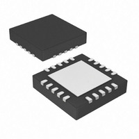
IC PIC MCU FLASH 256KX8 20-QFN
Manufacturer
Microchip Technology
Series
PIC® XLP™ 18Fr
Datasheets
1.PIC18LF13K22-ISS.pdf
(388 pages)
2.PIC18LF13K22-ISS.pdf
(12 pages)
3.PIC18LF13K22-ISS.pdf
(36 pages)
4.PIC18LF14K22-IP.pdf
(382 pages)
Specifications of PIC18LF13K22-I/ML
Program Memory Type
FLASH
Program Memory Size
8KB (4K x 16)
Package / Case
20-VQFN Exposed Pad, 20-HVQFN, 20-SQFN, 20-DHVQFN
Core Processor
PIC
Core Size
8-Bit
Speed
64MHz
Connectivity
I²C, LIN, SPI, UART/USART
Peripherals
Brown-out Detect/Reset, POR, PWM, WDT
Number Of I /o
17
Eeprom Size
256 x 8
Ram Size
256 x 8
Voltage - Supply (vcc/vdd)
1.8 V ~ 3.6 V
Data Converters
A/D 12x10b
Oscillator Type
Internal
Operating Temperature
-40°C ~ 85°C
Processor Series
PIC18LF
Core
PIC
Data Bus Width
8 bit
Data Ram Size
256 B
Interface Type
I2C, MSSP, SPI, USART
Maximum Clock Frequency
32 KHz
Number Of Programmable I/os
18
Number Of Timers
4
Operating Supply Voltage
1.8 V to 3.6 V
Maximum Operating Temperature
+ 125 C
Mounting Style
SMD/SMT
3rd Party Development Tools
52715-96, 52716-328, 52717-734, 52712-325, EWPIC18
Development Tools By Supplier
PG164130, DV164035, DV244005, DV164005
Minimum Operating Temperature
- 40 C
On-chip Adc
10 bit, 12 Channel
Lead Free Status / RoHS Status
Lead free / RoHS Compliant
Lead Free Status / RoHS Status
Lead free / RoHS Compliant, Lead free / RoHS Compliant
Available stocks
Company
Part Number
Manufacturer
Quantity
Price
Company:

Part Number:
PIC18LF13K22-I/ML
Manufacturer:
CAVIUM
Quantity:
155


3.4
The PGC pin is used as a clock input pin and the PGD
pin is used for entering command bits and data input/
output during serial operation. Commands and data are
transmitted on the rising edge of PGC, latched on the
falling edge of PGC and are Least Significant bit (LSb)
first.
3.4.1
All instructions are 20 bits, consisting of a leading 4-bit
command followed by a 16-bit operand, which depends
on the type of command being executed. To input a
command, PGC is cycled four times. The commands
needed for programming and verification are shown in
Table 3-2.
Depending on the 4-bit command, the 16-bit operand
represents 16 bits of input data or 8 bits of input data
and 8 bits of output data.
Throughout this specification, commands and data are
presented as illustrated in Table 3-3. The 4-bit
command, Most Significant bit (MSb), is shown first.
The command operand, or “Data Payload”, is shown
<MSB><LSB>. Figure 3-10 demonstrates how to
serially present a 20-bit command/operand to the
device.
3.4.2
The core instruction passes a 16-bit instruction to the
CPU core for execution. This is needed to set up
registers as appropriate for use with other commands.
TABLE 3-2:
© 2009 Microchip Technology Inc.
Core Instruction
(Shift in16-bit instruction)
Shift out TABLAT register
Table Read
Table Read, post-increment
Table Read, post-decrement
Table Read, pre-increment
Table Write
Table Write, post-increment by 2
Table Write, start programming,
post-increment by 2
Table Write, start programming
Serial Program/Verify Operation
4-BIT COMMANDS
CORE INSTRUCTION
Description
COMMANDS FOR
PROGRAMMING
Command
Advance Information
0000
0010
1000
1001
1010
1011
1100
1101
1110
1111
4-Bit
PIC18F1XK22/LF1XK22
DS41357B-page 9
Related parts for PIC18LF13K22-I/ML
Image
Part Number
Description
Manufacturer
Datasheet
Request
R

Part Number:
Description:
Manufacturer:
Microchip Technology Inc.
Datasheet:
Part Number:
Description:
Manufacturer:
Microchip Technology Inc.
Datasheet:
Part Number:
Description:
Manufacturer:
Microchip Technology Inc.
Datasheet:
Part Number:
Description:
Manufacturer:
Microchip Technology Inc.
Datasheet:
Part Number:
Description:
Manufacturer:
Microchip Technology Inc.
Datasheet:
Part Number:
Description:
Manufacturer:
Microchip Technology Inc.
Datasheet:
Part Number:
Description:
Manufacturer:
Microchip Technology Inc.
Datasheet:
Part Number:
Description:
Manufacturer:
Microchip Technology Inc.
Datasheet: