C8051F523A-IM Silicon Laboratories Inc, C8051F523A-IM Datasheet - Page 18
C8051F523A-IM
Manufacturer Part Number
C8051F523A-IM
Description
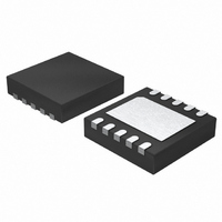
IC 8051 MCU 4K FLASH 10DFN
Manufacturer
Silicon Laboratories Inc
Series
C8051F52xr
Specifications of C8051F523A-IM
Program Memory Type
FLASH
Program Memory Size
4KB (4K x 8)
Package / Case
10-DFN
Core Processor
8051
Core Size
8-Bit
Speed
25MHz
Connectivity
LIN, SPI, UART/USART
Peripherals
Brown-out Detect/Reset, POR, PWM, Temp Sensor, WDT
Number Of I /o
6
Ram Size
256 x 8
Voltage - Supply (vcc/vdd)
1.8 V ~ 5.25 V
Data Converters
A/D 6x12b
Oscillator Type
Internal
Operating Temperature
-40°C ~ 125°C
Processor Series
C8051F5x
Core
8051
Data Bus Width
8 bit
Data Ram Size
256 B
Interface Type
SPI/UART
Maximum Clock Frequency
25 MHz
Number Of Programmable I/os
6
Number Of Timers
3
Maximum Operating Temperature
+ 125 C
Mounting Style
SMD/SMT
3rd Party Development Tools
PK51, CA51, A51, ULINK2
Development Tools By Supplier
C8051F500DK
Minimum Operating Temperature
- 40 C
On-chip Adc
6-ch x 12-bit
Lead Free Status / RoHS Status
Lead free / RoHS Compliant
For Use With
336-1488 - KIT DEV C8051F53XA, C8051F52XA770-1006 - ISP 4PORT FOR SILABS C8051F MCU336-1455 - ADAPTER PROGRAM TOOLSTICK F520
Eeprom Size
-
Lead Free Status / Rohs Status
Lead free / RoHS Compliant
Other names
336-1491-5


C8051F52x/F52xA/F53x/F53xA
1.2. CIP-51™ Microcontroller
1.2.1. Fully 8051 Compatible Instruction Set
The C8051F52x/F52xA/F53x/F53xA devices use Silicon Laboratories’ proprietary CIP-51 microcontroller
core. The CIP-51 is fully compatible with the MCS-51™ instruction set. Standard 803x/805x assemblers
and compilers can be used to develop software. The C8051F52x/F52xA/F53x/F53xA family has a superset
of all the peripherals included with a standard 8052.
1.2.2. Improved Throughput
The CIP-51 employs a pipelined architecture that greatly increases its instruction throughput over the stan-
dard 8051 architecture. In a standard 8051, all instructions except for MUL and DIV take 12 or 24 system
clock cycles to execute, and usually have a maximum system clock of 12-to-24 MHz. By contrast, the CIP-
51 core executes 70% of its instructions in one or two system clock cycles, with no instructions taking more
than eight system clock cycles.
With the CIP-51's system clock running at 25 MHz, it has a peak throughput of 25 MIPS. The CIP-51 has a
total of 109 instructions. The table below shows the total number of instructions that require each execution
time.
1.2.3. Additional Features
The C8051F52x/F52xA/F53x/F53xA family includes several key enhancements to the CIP-51 core and
peripherals to improve performance and ease of use in end applications.
An extended interrupt handler allows the numerous analog and digital peripherals to operate indepen-
dently of the controller core and interrupt the controller only when necessary. By requiring less intervention
from the microcontroller core, an interrupt-driven system is more efficient and allows for easier implemen-
tation of multi-tasking, real-time systems.
Eight reset sources are available: power-on reset circuitry (POR), an on-chip V
Timer, a Missing Clock Detector, a voltage level detection from Comparator, a forced software reset, an
external reset pin, and an illegal Flash access protection circuit. Each reset source except for the POR,
Reset Input Pin, or Flash error may be disabled by the user in software. The WDT may be permanently
enabled in software after a power-on reset during MCU initialization.
The internal oscillator is factory calibrated to 24.5 MHz ±0.5% across the entire operating temperature and
voltage range. An external oscillator drive circuit is also included, allowing an external crystal, ceramic res-
onator, capacitor, RC, or CMOS clock source to generate the system clock.
1.2.4. On-Chip Debug Circuitry
The C8051F52x/F52xA/F53x/F53xA devices include on-chip Silicon Laboratories 2-Wire (C2) debug cir-
cuitry that provides non-intrusive, full speed, in-circuit debugging of the production part installed in the end
application.
Silicon Laboratories’ debugging system supports inspection and modification of memory and registers,
breakpoints, and single stepping. No additional target RAM, program memory, timers, or communications
channels are required. All the digital and analog peripherals are functional and work correctly while debug-
ging. All the peripherals (except for the ADC) are stalled when the MCU is halted, during single stepping,
or at a breakpoint in order to keep them synchronized.
The C8051F410DK development kit provides all the hardware and software necessary to develop applica-
tion code and perform in-circuit debugging with the C8051F52x/F52xA/F53x/F53xA MCUs. The kit
18
Clocks to Execute
Number of Instructions
1
26
2
50
2/3
5
Rev. 1.3
3
14
3/4
7
4
3
4/5
1
DD
monitor, a Watchdog
5
2
8
1
Related parts for C8051F523A-IM
Image
Part Number
Description
Manufacturer
Datasheet
Request
R

Part Number:
Description:
SMD/C°/SINGLE-ENDED OUTPUT SILICON OSCILLATOR
Manufacturer:
Silicon Laboratories Inc
Part Number:
Description:
Manufacturer:
Silicon Laboratories Inc
Datasheet:
Part Number:
Description:
N/A N/A/SI4010 AES KEYFOB DEMO WITH LCD RX
Manufacturer:
Silicon Laboratories Inc
Datasheet:
Part Number:
Description:
N/A N/A/SI4010 SIMPLIFIED KEY FOB DEMO WITH LED RX
Manufacturer:
Silicon Laboratories Inc
Datasheet:
Part Number:
Description:
N/A/-40 TO 85 OC/EZLINK MODULE; F930/4432 HIGH BAND (REV E/B1)
Manufacturer:
Silicon Laboratories Inc
Part Number:
Description:
EZLink Module; F930/4432 Low Band (rev e/B1)
Manufacturer:
Silicon Laboratories Inc
Part Number:
Description:
I°/4460 10 DBM RADIO TEST CARD 434 MHZ
Manufacturer:
Silicon Laboratories Inc
Part Number:
Description:
I°/4461 14 DBM RADIO TEST CARD 868 MHZ
Manufacturer:
Silicon Laboratories Inc
Part Number:
Description:
I°/4463 20 DBM RFSWITCH RADIO TEST CARD 460 MHZ
Manufacturer:
Silicon Laboratories Inc
Part Number:
Description:
I°/4463 20 DBM RADIO TEST CARD 868 MHZ
Manufacturer:
Silicon Laboratories Inc
Part Number:
Description:
I°/4463 27 DBM RADIO TEST CARD 868 MHZ
Manufacturer:
Silicon Laboratories Inc
Part Number:
Description:
I°/4463 SKYWORKS 30 DBM RADIO TEST CARD 915 MHZ
Manufacturer:
Silicon Laboratories Inc
Part Number:
Description:
N/A N/A/-40 TO 85 OC/4463 RFMD 30 DBM RADIO TEST CARD 915 MHZ
Manufacturer:
Silicon Laboratories Inc
Part Number:
Description:
I°/4463 20 DBM RADIO TEST CARD 169 MHZ
Manufacturer:
Silicon Laboratories Inc