M38227ECFP Renesas Electronics America, M38227ECFP Datasheet - Page 20
M38227ECFP
Manufacturer Part Number
M38227ECFP
Description
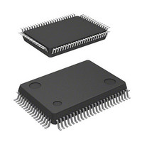
IC 740 MCU EPROM 48K 80QFP
Manufacturer
Renesas Electronics America
Series
740/38000r
Datasheet
1.M38227ECFP.pdf
(82 pages)
Specifications of M38227ECFP
Core Processor
740
Core Size
8-Bit
Speed
8MHz
Connectivity
SIO, UART/USART
Peripherals
LCD
Number Of I /o
49
Program Memory Size
48KB (48K x 8)
Program Memory Type
OTP
Ram Size
1K x 8
Voltage - Supply (vcc/vdd)
2.5 V ~ 5.5 V
Data Converters
A/D 8x8b
Oscillator Type
Internal
Operating Temperature
-20°C ~ 85°C
Package / Case
80-QFP
Lead Free Status / RoHS Status
Contains lead / RoHS non-compliant
Eeprom Size
-
Available stocks
Company
Part Number
Manufacturer
Quantity
Price
Company:

Part Number:
M38227ECFP
Manufacturer:
Renesas Electronics America
Quantity:
10 000
Part Number:
M38227ECFP
Manufacturer:
MIT
Quantity:
20 000
Company:
Part Number:
M38227ECFP#U0
Manufacturer:
Renesas Electronics America
Quantity:
10 000
Part Number:
M38227ECFP#U0
Manufacturer:
RENESAS/瑞萨
Quantity:
20 000


I/O PORTS
Direction Registers (ports P2, P4
P5-P7)
The 3822 group has 49 programmable I/O pins arranged in seven
I/O ports (ports P0–P2, P4
P4
input/output direction of each individual pin. Each bit in a direction
register corresponds to one pin, and each pin can be set to be in-
put port or output port.
When “0” is written to the bit corresponding to a pin, that pin be-
comes an input pin. When “1” is written to that bit, that pin be-
comes an output pin.
If data is read from a pin set to output, the value of the port output
latch is read, not the value of the pin itself. Pins set to input are
floating. If a pin set to input is written to, only the port output latch
is written to and the pin remains floating.
Direction Registers (ports P0 and P1)
Ports P0 and P1 have direction registers which determine the in-
put/output direction of each individual port.
Each port in a direction register corresponds to one port, each port
can be set to be input or output. When “0” is written to the bit 0 of
a direction register, that port becomes an input port. When “1” is
written to that port, that port becomes an output port. Bits 1 to 7 of
ports P0 and P1 direction registers are not used.
Ports P3 and P4
These ports are only for input.
Pull-up/Pull-down Control
By setting the PULL register A (address 0016
ister B (address 0017
either pull-down or pull-up (pins that are shared with the segment
output pins for LCD are pull-down; all other pins are pull-up) with
a program.
However, the contents of PULL register A and PULL register B do
not affect ports programmed as the output ports.
1
–P4
7
and P5-P7 have direction registers which determine the
16
0
), ports except for port P4
1
–P4
7
and P5-P7). The I/O ports P2,
16
) or the PULL reg-
1
-P4
0
can control
7
, and
Fig. 14 Structure of PULL register A and PULL register B
b 7
b7
Note: The contents of PULL register A and PULL register B
SINGLE-CHIP 8-BIT CMOS MICROCOMPUTER
do not affect ports programmed as the output port.
MITSUBISHI MICROCOMPUTERS
b 0
b 0
P U L L r e g i s t e r A
( P U L L A : a d d r e s s 0 0 1 6
P U L L r e g i s t e r B
( P U L L B : a d d r e s s 0 0 1 7
P0
P1
P2
P3
P7
Not used (return “0” when read)
P4
P4
P5
P5
P6
P6
Not used (return “0” when read)
0
0
0
4
0
1
4
0
4
0
4
–P0
–P1
–P2
–P3
, P7
–P4
–P4
–P5
–P5
–P6
–P6
7
7
7
7
1
3
7
3
7
3
7
pull-down
pull-down
pull-up
pull-down
pull-up
pull-up
pull-up
pull-up
pull-up
pull-up
pull-up
3822 Group
0 : D i s a b l e
1 : E n a b l e
1 6
1 6
)
)
17
Related parts for M38227ECFP
Image
Part Number
Description
Manufacturer
Datasheet
Request
R

Part Number:
Description:
KIT STARTER FOR M16C/29
Manufacturer:
Renesas Electronics America
Datasheet:

Part Number:
Description:
KIT STARTER FOR R8C/2D
Manufacturer:
Renesas Electronics America
Datasheet:

Part Number:
Description:
R0K33062P STARTER KIT
Manufacturer:
Renesas Electronics America
Datasheet:

Part Number:
Description:
KIT STARTER FOR R8C/23 E8A
Manufacturer:
Renesas Electronics America
Datasheet:

Part Number:
Description:
KIT STARTER FOR R8C/25
Manufacturer:
Renesas Electronics America
Datasheet:

Part Number:
Description:
KIT STARTER H8S2456 SHARPE DSPLY
Manufacturer:
Renesas Electronics America
Datasheet:

Part Number:
Description:
KIT STARTER FOR R8C38C
Manufacturer:
Renesas Electronics America
Datasheet:

Part Number:
Description:
KIT STARTER FOR R8C35C
Manufacturer:
Renesas Electronics America
Datasheet:

Part Number:
Description:
KIT STARTER FOR R8CL3AC+LCD APPS
Manufacturer:
Renesas Electronics America
Datasheet:
Part Number:
Description:
KIT STARTER FOR RX610
Manufacturer:
Renesas Electronics America
Datasheet:

Part Number:
Description:
KIT STARTER FOR R32C/118
Manufacturer:
Renesas Electronics America
Datasheet:

Part Number:
Description:
KIT DEV RSK-R8C/26-29
Manufacturer:
Renesas Electronics America
Datasheet:

Part Number:
Description:
KIT STARTER FOR SH7124
Manufacturer:
Renesas Electronics America
Datasheet:

Part Number:
Description:
KIT STARTER FOR H8SX/1622
Manufacturer:
Renesas Electronics America
Datasheet:

Part Number:
Description:
KIT DEV FOR SH7203
Manufacturer:
Renesas Electronics America
Datasheet: