PIC16C770/JW Microchip Technology, PIC16C770/JW Datasheet - Page 115
PIC16C770/JW
Manufacturer Part Number
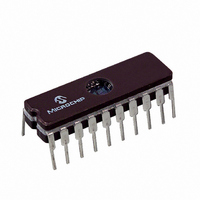
PIC16C770/JW
Description
IC MCU EPROM2KX14 A/D PWM 20CDIP
Manufacturer
Microchip Technology
Series
PIC® 16Cr
Datasheets
1.PIC16C770-ISO.pdf
(220 pages)
2.PIC16C770-ISO.pdf
(6 pages)
3.PIC16C770-ISO.pdf
(8 pages)
Specifications of PIC16C770/JW
Core Processor
PIC
Core Size
8-Bit
Speed
20MHz
Connectivity
I²C, SPI
Peripherals
Brown-out Detect/Reset, POR, PWM, WDT
Number Of I /o
15
Program Memory Size
3.5KB (2K x 14)
Program Memory Type
EPROM, UV
Ram Size
256 x 8
Voltage - Supply (vcc/vdd)
4 V ~ 5.5 V
Data Converters
A/D 6x12b
Oscillator Type
Internal
Operating Temperature
0°C ~ 70°C
Package / Case
20-CDIP (0.300", 7.62mm) Window
For Use With
DVA16XP200 - ADAPTER ICE 20DIP/SOIC/SSOPAC164028 - MODULE SKT PROMATEII 20SOIC/DIP
Lead Free Status / RoHS Status
Contains lead / RoHS non-compliant
Eeprom Size
-


11.6
11.6.1
The maximum recommended impedance for ana-
log sources is 2.5 k . This value is calculated based
on the maximum leakage current of the input pin. The
leakage current is 100 nA max., and the analog input
voltage cannot be varied by more than 1/4 LSb or
250 V due to leakage. This places a requirement on
the input impedance of 250 V/100 nA = 2.5 k .
11.6.2
For the A/D converter to meet its specified accuracy,
the charge holding capacitor (C
to fully charge to the input channel voltage level. The
analog input model is shown in Figure 11-5. The source
impedance (R
impedance directly affect the time required to charge
the capacitor C
impedance varies over the device voltage (V
Figure 11-5. The maximum recommended imped-
ance for analog sources is 2.5 k . After the analog
input channel is selected (changed) this sampling must
be done before the conversion can be started.
To calculate the minimum sampling time, Equation 11-
2 may be used. This equation assumes that 1/4 LSb
error is used (16384 steps for the A/D). The 1/4 LSb
error is the maximum error allowed for the A/D to meet
its specified resolution.
The C
A/D.
2002 Microchip Technology Inc.
HOLD
A/D Sample Requirements
RECOMMENDED SOURCE
IMPEDANCE
SAMPLING TIME CALCULATION
is assumed to be 25 pF for the 12-bit
S
) and the internal sampling switch (R
HOLD
. The sampling switch (R
HOLD
) must be allowed
DD
), see
SS
SS
)
)
EXAMPLE 11-2:
Figure 11-3 shows the calculation of the minimum time
required to charge C
the following system assumptions:
V
V
V
Solving for T
T
C
R
1/4 LSb error
V
Temp (system Max.) = 50 C
Note 1: The reference voltage (V
C
H OL D
R EF
R EF
DD
HOLD
S
PIC16C717/770/771
=
= 2.5 k
–
–
= 5V
1
C
--------------- -
16384
V
=
–
H O LD
R EF
= 25 pF
2: The charge holding capacitor (C
3: The maximum recommended impedance
--------------- -
16384
V
R E F
C
1
effect on the equation, since it cancels
itself out.
not discharged after each conversion.
for analog sources is 2.5 k . This is
required to meet the pin leakage specifi-
cation.
:
=
1k
–
R
--------------- -
16384
V
=
V
+
SS
R E F
R E F
R
V
S S
= 10 k (worst case)
R E F
HOLD
+
A/D SAMPLING TIME
EQUATION
1 e
R
–
S
1 e
. This calculation is based on
–
ln
------------------------------------------------------------------ -
C
H O LD
--------------- -
16384
------------------------------------------------------------------ -
C
H O LD
1
R
I C
DS41120B-page 113
–
T
R
+
C
I C
–
R
T
+
REF
S S
C
R
+
SS
) has no
R
+
HOLD
S
R
S
) is
Related parts for PIC16C770/JW
Image
Part Number
Description
Manufacturer
Datasheet
Request
R

Part Number:
Description:
IC MCU OTP 8KX14 A/D PWM 44PLCC
Manufacturer:
Microchip Technology
Datasheet:
Part Number:
Description:
IC MCU OTP 8KX14 A/D PWM 44PLCC
Manufacturer:
Microchip Technology
Datasheet:

Part Number:
Description:
IC MCU OTP 8KX14 A/D PWM 44TQFP
Manufacturer:
Microchip Technology
Datasheet:

Part Number:
Description:
IC MCU OTP 8KX14 A/D PWM 44-MQFP
Manufacturer:
Microchip Technology
Datasheet:

Part Number:
Description:
IC MCU OTP 8KX14 A/D PWM 40DIP
Manufacturer:
Microchip Technology
Datasheet:
Part Number:
Description:
IC MCU OTP 8KX14 A/D PWM 44PLCC
Manufacturer:
Microchip Technology
Datasheet:
Part Number:
Description:
IC MCU OTP 8KX14 A/D PWM 40DIP
Manufacturer:
Microchip Technology
Datasheet:
Part Number:
Description:
IC MCU OTP 8KX14 A/D PWM 40DIP
Manufacturer:
Microchip Technology
Datasheet:
Part Number:
Description:
IC MCU OTP 8KX14 A/D PWM 40DIP
Manufacturer:
Microchip Technology
Datasheet:
Part Number:
Description:
IC MCU OTP 8KX14 A/D PWM 44PLCC
Manufacturer:
Microchip Technology
Datasheet:
Part Number:
Description:
IC MCU OTP 8KX14 A/D PWM 44PLCC
Manufacturer:
Microchip Technology
Datasheet:
Part Number:
Description:
IC MCU OTP 8KX14 A/D PWM 44-MQFP
Manufacturer:
Microchip Technology
Datasheet:
Part Number:
Description:
IC MCU OTP 8KX14 A/D PWM 40DIP
Manufacturer:
Microchip Technology
Datasheet:
Part Number:
Description:
IC MCU OTP 8KX14 A/D PWM 44-MQFP
Manufacturer:
Microchip Technology
Datasheet:
Part Number:
Description:
IC MCU OTP 8KX14 A/D PWM 40DIP
Manufacturer:
Microchip Technology
Datasheet: