PIC16C770/JW Microchip Technology, PIC16C770/JW Datasheet - Page 27
PIC16C770/JW
Manufacturer Part Number
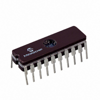
PIC16C770/JW
Description
IC MCU EPROM2KX14 A/D PWM 20CDIP
Manufacturer
Microchip Technology
Series
PIC® 16Cr
Datasheets
1.PIC16C770-ISO.pdf
(220 pages)
2.PIC16C770-ISO.pdf
(6 pages)
3.PIC16C770-ISO.pdf
(8 pages)
Specifications of PIC16C770/JW
Core Processor
PIC
Core Size
8-Bit
Speed
20MHz
Connectivity
I²C, SPI
Peripherals
Brown-out Detect/Reset, POR, PWM, WDT
Number Of I /o
15
Program Memory Size
3.5KB (2K x 14)
Program Memory Type
EPROM, UV
Ram Size
256 x 8
Voltage - Supply (vcc/vdd)
4 V ~ 5.5 V
Data Converters
A/D 6x12b
Oscillator Type
Internal
Operating Temperature
0°C ~ 70°C
Package / Case
20-CDIP (0.300", 7.62mm) Window
For Use With
DVA16XP200 - ADAPTER ICE 20DIP/SOIC/SSOPAC164028 - MODULE SKT PROMATEII 20SOIC/DIP
Lead Free Status / RoHS Status
Contains lead / RoHS non-compliant
Eeprom Size
-


3.0
Some pins for these I/O ports are multiplexed with an
alternate function for the peripheral features on the
device. In general, when a peripheral is enabled, that
pin may not be used as a general purpose I/O pin.
Additional information on I/O ports may be found in the
PICmicro™ Mid-Range MCU Family Reference Man-
ual, (DS33023).
3.1
The PIC16C717/770/771 have two I/O ports: PORTA
and PORTB. Some of these port pins are mixed-signal
(can be digital or analog). When an analog signal is
REGISTER 3-1:
3.2
PORTA is a 8-bit wide bi-directional port. The corre-
sponding data direction register is TRISA. Setting a
TRISA bit (=1) will make the corresponding PORTA pin
an input (i.e., put the corresponding output driver in a
Hi-impedance mode). Clearing a TRISA bit (=0) will
make the corresponding PORTA pin an output (i.e., put
the contents of the output latch on the selected pin).
Reading the PORTA register reads the status of the
pins, whereas writing to it will write to the port latch. All
write operations are read-modify-write operations.
Therefore, a write to a port implies that the port pins are
read, this value is modified, and then written to the port
data latch.
Pins RA<3:0> are multiplexed with analog functions,
such as analog inputs to the A/D converter, analog
V
puts. When the analog peripherals are using any of
REF
2002 Microchip Technology Inc.
inputs, and the onboard bandgap reference out-
I/O PORTS
I/O Port Analog/Digital Mode
PORTA and the TRISA Register
bit 7-6
bit 5-0
ANALOG SELECT REGISTER (ANSEL: 9Dh)
Reserved: Do not use
ANS<5:0>: Analog Select between analog or digital function on pins AN<5:0>, respectively.
0 = Digital I/O. Pin is assigned to port or special function.
1 = Analog Input. Pin is assigned as analog input.
bit 7
Legend:
R = Readable bit
- n = Value at POR
Note:
R/W-1
—
Setting a pin to an analog input disables the digital input buffer on the pin. The cor-
responding TRIS bit should be set to Input mode when using pins as analog inputs.
R/W-1
—
R/W-1
ANS5
W = Writable bit
’1’ = Bit is set
R/W-1
ANS4
present on a pin, the pin must be configured as an ana-
log input to prevent unnecessary current draw from the
power supply. The Analog Select Register (ANSEL)
allows the user to individually select the Digital/Analog
mode on these pins. When the Analog mode is active,
the port pin will always read 0.
these pins as analog input/output, the ANSEL register
must have the proper value to individually select the
Analog mode of the corresponding pins.
Pin RA4 is multiplexed with the Timer0 module clock
input to become the RA4/T0CKI pin. The RA4/T0CKI
pin is a Schmitt Trigger input and an open drain output.
Pin RA5 is multiplexed with the device RESET (MCLR)
and programming input (V
MCLR/V
buffer. All other RA port pins have Schmitt Trigger input
buffers and full CMOS output buffers.
Pins RA6 and RA7 are multiplexed with the oscillator
input and output functions.
The TRISA register controls the direction of the RA
pins, even when they are being used as analog inputs.
The user must ensure the bits in the TRISA register are
maintained set when using them as analog inputs.
Note:
Note 1: On a Power-on Reset, the ANSEL regis-
PIC16C717/770/771
PP
2: If a pin is configured as Analog mode, the
U = Unimplemented bit, read as ‘0’
’0’ = Bit is cleared
R/W-1
ANS3
Upon RESET, the ANSEL register config-
ures the RA<3:0> pins as analog inputs.
All RA<3:0> pins will read as '0'.
input only pin has a Schmitt Trigger input
ter configures these mixed-signal pins as
Analog mode.
RA pin will always read '0' and RB pin will
always read '1', even if the digital output is
active.
R/W-1
ANS2
PP
) functions. The RA5/
x = Bit is unknown
R/W-1
ANS1
DS41120B-page 25
R/W-1
ANS0
bit 0
Related parts for PIC16C770/JW
Image
Part Number
Description
Manufacturer
Datasheet
Request
R

Part Number:
Description:
IC MCU OTP 8KX14 A/D PWM 44PLCC
Manufacturer:
Microchip Technology
Datasheet:
Part Number:
Description:
IC MCU OTP 8KX14 A/D PWM 44PLCC
Manufacturer:
Microchip Technology
Datasheet:

Part Number:
Description:
IC MCU OTP 8KX14 A/D PWM 44TQFP
Manufacturer:
Microchip Technology
Datasheet:

Part Number:
Description:
IC MCU OTP 8KX14 A/D PWM 44-MQFP
Manufacturer:
Microchip Technology
Datasheet:

Part Number:
Description:
IC MCU OTP 8KX14 A/D PWM 40DIP
Manufacturer:
Microchip Technology
Datasheet:
Part Number:
Description:
IC MCU OTP 8KX14 A/D PWM 44PLCC
Manufacturer:
Microchip Technology
Datasheet:
Part Number:
Description:
IC MCU OTP 8KX14 A/D PWM 40DIP
Manufacturer:
Microchip Technology
Datasheet:
Part Number:
Description:
IC MCU OTP 8KX14 A/D PWM 40DIP
Manufacturer:
Microchip Technology
Datasheet:
Part Number:
Description:
IC MCU OTP 8KX14 A/D PWM 40DIP
Manufacturer:
Microchip Technology
Datasheet:
Part Number:
Description:
IC MCU OTP 8KX14 A/D PWM 44PLCC
Manufacturer:
Microchip Technology
Datasheet:
Part Number:
Description:
IC MCU OTP 8KX14 A/D PWM 44PLCC
Manufacturer:
Microchip Technology
Datasheet:
Part Number:
Description:
IC MCU OTP 8KX14 A/D PWM 44-MQFP
Manufacturer:
Microchip Technology
Datasheet:
Part Number:
Description:
IC MCU OTP 8KX14 A/D PWM 40DIP
Manufacturer:
Microchip Technology
Datasheet:
Part Number:
Description:
IC MCU OTP 8KX14 A/D PWM 44-MQFP
Manufacturer:
Microchip Technology
Datasheet:
Part Number:
Description:
IC MCU OTP 8KX14 A/D PWM 40DIP
Manufacturer:
Microchip Technology
Datasheet: