PIC16C770/JW Microchip Technology, PIC16C770/JW Datasheet - Page 129
PIC16C770/JW
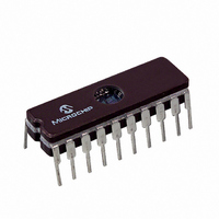
Manufacturer Part Number
PIC16C770/JW
Description
IC MCU EPROM2KX14 A/D PWM 20CDIP
Manufacturer
Microchip Technology
Series
PIC® 16Cr
Datasheets
1.PIC16C770-ISO.pdf
(220 pages)
2.PIC16C770-ISO.pdf
(6 pages)
3.PIC16C770-ISO.pdf
(8 pages)
Specifications of PIC16C770/JW
Core Processor
PIC
Core Size
8-Bit
Speed
20MHz
Connectivity
I²C, SPI
Peripherals
Brown-out Detect/Reset, POR, PWM, WDT
Number Of I /o
15
Program Memory Size
3.5KB (2K x 14)
Program Memory Type
EPROM, UV
Ram Size
256 x 8
Voltage - Supply (vcc/vdd)
4 V ~ 5.5 V
Data Converters
A/D 6x12b
Oscillator Type
Internal
Operating Temperature
0°C ~ 70°C
Package / Case
20-CDIP (0.300", 7.62mm) Window
For Use With
DVA16XP200 - ADAPTER ICE 20DIP/SOIC/SSOPAC164028 - MODULE SKT PROMATEII 20SOIC/DIP
Lead Free Status / RoHS Status
Contains lead / RoHS non-compliant
Eeprom Size
-


12.10 Interrupts
The devices have up to 11 sources of interrupt. The
interrupt control register (INTCON) records individual
interrupt requests in flag bits. It also has individual and
global interrupt enable bits.
A Global Interrupt Enable bit, GIE (INTCON<7>),
enables (if set) all un-masked interrupts or disables (if
cleared) all interrupts. When bit GIE is enabled and an
interrupt’s flag bit and mask bit are set, the interrupt will
vector immediately. Individual interrupts can be dis-
abled through their corresponding enable bits in vari-
ous registers. Individual interrupt bits are set,
regardless of the status of the GIE bit. The GIE bit is
cleared on RESET.
The “return from interrupt” instruction, RETFIE, exits
the interrupt routine as well as sets the GIE bit, which
re-enables interrupts.
FIGURE 12-10:
Note:
2002 Microchip Technology Inc.
BCLIF
BCLIE
LVDIF
LVDIE
TMR1IF
TMR1IE
Individual interrupt flag bits are set regard-
less of the status of their corresponding
mask bit or the GIE bit.
ADIF
ADIE
TMR2IF
TMR2IE
INTERRUPT LOGIC
CCP1IF
CCP1IE
SSPIF
SSPIE
T0IF
T0IE
INTF
INTE
RBIF
RBIE
PEIE
GIE
The RB0/INT pin interrupt, the RB port change interrupt
and the TMR0 overflow interrupt flags are contained in
the INTCON register.
The peripheral interrupt flags are contained in the spe-
cial function registers PIR1 and PIR2. The correspond-
ing interrupt enable bits are contained in special
function registers PIE1 and PIE2, and the peripheral
interrupt enable bit is contained in special function reg-
ister INTCON.
When an interrupt is responded to, the GIE bit is
cleared to disable any further interrupt, the return
address is pushed onto the stack and the PC is loaded
with 0004h. Once in the interrupt service routine the
source(s) of the interrupt can be determined by polling
the interrupt flag bits. The interrupt flag bit(s) must be
cleared in software before re-enabling interrupts to
avoid recursive interrupts.
For external interrupt events, such as the INT pin or
PORTB change interrupt, the interrupt latency will be
three or four instruction cycles. The exact latency
depends when the interrupt event occurs. The latency
is the same for one or two cycle instructions. Individual
interrupt flag bits are set regardless of the status of their
corresponding mask bit or the GIE bit
PIC16C717/770/771
Wake-up (If in SLEEP mode)
DS41120B-page 127
Interrupt to CPU
Related parts for PIC16C770/JW
Image
Part Number
Description
Manufacturer
Datasheet
Request
R

Part Number:
Description:
IC MCU OTP 8KX14 A/D PWM 44PLCC
Manufacturer:
Microchip Technology
Datasheet:
Part Number:
Description:
IC MCU OTP 8KX14 A/D PWM 44PLCC
Manufacturer:
Microchip Technology
Datasheet:

Part Number:
Description:
IC MCU OTP 8KX14 A/D PWM 44TQFP
Manufacturer:
Microchip Technology
Datasheet:

Part Number:
Description:
IC MCU OTP 8KX14 A/D PWM 44-MQFP
Manufacturer:
Microchip Technology
Datasheet:

Part Number:
Description:
IC MCU OTP 8KX14 A/D PWM 40DIP
Manufacturer:
Microchip Technology
Datasheet:
Part Number:
Description:
IC MCU OTP 8KX14 A/D PWM 44PLCC
Manufacturer:
Microchip Technology
Datasheet:
Part Number:
Description:
IC MCU OTP 8KX14 A/D PWM 40DIP
Manufacturer:
Microchip Technology
Datasheet:
Part Number:
Description:
IC MCU OTP 8KX14 A/D PWM 40DIP
Manufacturer:
Microchip Technology
Datasheet:
Part Number:
Description:
IC MCU OTP 8KX14 A/D PWM 40DIP
Manufacturer:
Microchip Technology
Datasheet:
Part Number:
Description:
IC MCU OTP 8KX14 A/D PWM 44PLCC
Manufacturer:
Microchip Technology
Datasheet:
Part Number:
Description:
IC MCU OTP 8KX14 A/D PWM 44PLCC
Manufacturer:
Microchip Technology
Datasheet:
Part Number:
Description:
IC MCU OTP 8KX14 A/D PWM 44-MQFP
Manufacturer:
Microchip Technology
Datasheet:
Part Number:
Description:
IC MCU OTP 8KX14 A/D PWM 40DIP
Manufacturer:
Microchip Technology
Datasheet:
Part Number:
Description:
IC MCU OTP 8KX14 A/D PWM 44-MQFP
Manufacturer:
Microchip Technology
Datasheet:
Part Number:
Description:
IC MCU OTP 8KX14 A/D PWM 40DIP
Manufacturer:
Microchip Technology
Datasheet: