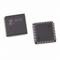
Z86D7308VSC1987 Zilog, Z86D7308VSC1987 Datasheet - Page 57

Z86D7308VSC1987
Manufacturer Part Number
Z86D7308VSC1987
Description
IC 32K OTP 3 VOLT 44-PLCC
Manufacturer
Zilog
Series
Z8® IRr
Datasheet
1.Z86D7308PSC1987.pdf
(92 pages)
Specifications of Z86D7308VSC1987
Core Processor
Z8
Core Size
8-Bit
Speed
8MHz
Peripherals
Brown-out Detect/Reset, LVD, POR, WDT
Number Of I /o
31
Program Memory Size
32KB (32K x 8)
Program Memory Type
OTP
Ram Size
236 x 8
Voltage - Supply (vcc/vdd)
2 V ~ 3.6 V
Oscillator Type
Internal
Operating Temperature
0°C ~ 70°C
Package / Case
44-LCC (J-Lead)
Lead Free Status / RoHS Status
Contains lead / RoHS non-compliant
Eeprom Size
-
Data Converters
-
Connectivity
-
PS019401-1102
Note:
This T16 mode is generally used to measure space time, the length of time
between bursts of carrier signal (marks).
If D6 of CTR2 Is 1
T16 ignores the subsequent edges in the input signal and continues counting
down. A timeout of T8 causes T16 to capture its current value and generate an
interrupt if enabled (CTR2, D2). In this case, T16 does not reload and continues
counting. If the D6 bit of CTR2 is toggled (by writing a 0 then a 1 to it), T16 cap-
tures and reloads on the next edge (rising, falling, or both depending on CTR1,
D5; D4), continuing to ignore subsequent edges.
This T16 mode is generally used to measure mark time, the length of an active
carrier signal burst.
If T16 reaches 0, T16 continues counting from
(CTR2 D5) is set, and an interrupt timeout can be generated if enabled (CTR2
D1).
Ping-Pong Mode
This operation mode is only valid in Transmit Mode. T8 and T16 must be pro-
grammed in Single-Pass Mode (CTR0, D6; CTR2, D6), and Ping-Pong Mode
must be programmed in CTR1, D3; D2. The user can begin the operation by
enabling either T8 or T16 (CTR0, D7 or CTR2, D7). For example, if T8 is enabled,
T8_OUT is set to this initial value (CTR1, D1). According to T8_OUT's level,
TC8H or TC8L is loaded into T8. After the terminal count is reached, T8 is dis-
abled, and T16 is enabled. T16_OUT then switches to its initial value (CTR1, D0),
data from TC16H and TC16L is loaded, and T16 starts to count. After T16 reaches
the terminal count, it stops, T8 is enabled again, repeating the entire cycle. Inter-
rupts can be allowed when T8 or T16 reaches terminal control (CTR0, D1; CTR2,
D1). To stop the Ping-Pong operation, write 00 to bits D3 and D2 of CTR1. See
Figure 29.
Enabling Ping-Pong operation while the counter/timers are
running might cause intermittent counter/timer function. Disable
the counter/timers and then reset the status flags before
instituting this operation.
P
R
E
L
I
M
I
N
A
40/44/48-Pin Low-Voltage IR OTP
FFFFh
R
Y
. Meanwhile, a status bit
Z86D73
51


