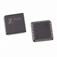
Z8F1601VN020SC Zilog, Z8F1601VN020SC Datasheet - Page 13

Z8F1601VN020SC
Manufacturer Part Number
Z8F1601VN020SC
Description
IC ENCORE MCU FLASH 16K 44-PLCC
Manufacturer
Zilog
Series
Encore!®r
Specifications of Z8F1601VN020SC
Core Processor
Z8
Core Size
8-Bit
Speed
20MHz
Connectivity
I²C, IrDA, SPI, UART/USART
Peripherals
Brown-out Detect/Reset, DMA, POR, PWM, WDT
Number Of I /o
31
Program Memory Size
16KB (16K x 8)
Program Memory Type
FLASH
Ram Size
2K x 8
Voltage - Supply (vcc/vdd)
3 V ~ 3.6 V
Data Converters
A/D 8x10b
Oscillator Type
Internal
Operating Temperature
0°C ~ 70°C
Package / Case
44-LCC (J-Lead)
Lead Free Status / RoHS Status
Contains lead / RoHS non-compliant
Eeprom Size
-
Other names
269-3129
Available stocks
Company
Part Number
Manufacturer
Quantity
Price
Table 3. Z8F6403 Errata for Devices with Date Codes 0226 and Earlier (Continued)
UP004207-0308
Sl
No
2
3
4
5
6
Summary
First cycle of Pulse-
Width Modulator
(PWM) output is
incorrect, but all
subsequent cycles
operate properly.
Timer interrupts in
CAPTURE or CAP-
TURE/COMPARE
mode may not clear
properly.
ADC output values
are one-half the
measured value.
ADC output is
inaccurate for input
values below
approximately
50 mV.
Power-On Reset
(POR) voltage
threshold does not
meet specification.
Errata to Z8F640x, Z8F480x, Z8F320x, Z8F240x, Z8F160x (Z8 Encore!
Description
The TIOI bit, which sets the initial state of the timer output, also sets the
transition when the counter reaches the PWM value. Thus, no transition
occurs the first time the counter reaches the PWM value.
Workaround
During timer initialization, the 16-bit Reload value must be written into the
Timer High and Low byte registers. This write causes a reload to happen as
soon as the timer is enabled, forcing timer out to its proper state.
When the counter is in capture or capture/compare mode the interrupt to the
IRQ controller is held from the time the count matches until the pre-scaler
times out. Thus the interrupt can be held for as much as 1-128 (Depending
upon the pre-scale value) cycles. If CPU services the interrupt before the
pre-scaler has timed out, the interrupt is not cleared automatically. Also just
clearing the bit does not work as well since the interrupt is not de-asserted
until the pre-scaler decrements to 0. The ISR must continually clear the bit
until it stays cleared.
Workaround
The ISR must clear the IRQ bit and then verify that it stayed cleared. If it is not
cleared then it repeat the process until the IRQ bit stays cleared.
The ADC exhibits a gain error that results in the output value being one-half
the actual measured value.
Workaround
Left shifting the 10-bit value converts (equivalent to a multiply by 2) scales the
ADC output properly. Alternatively, the 10-bit ADC data can be read as
(ADC_DATAH[6:0], ADC_DATAL[7:5]). ADC_DATAL bit 5 is not indicated in
the Product Specification, but does function as an extra bit in the current
silicon for test purposes.
The output from the ADC can vary widely when the input signal drops below
about 30 mV to 50 mV.
Workaround
Measure analog inputs only above 50 mV.
The POR voltage threshold is approximately 3.1 V which can prevent proper
operation with power supplies below 3.1 V.
Workaround
On power-up, insure that the power supply is kept between 3.2 V and 3.6 V
during operation.
Page 13 of 15
®
)


