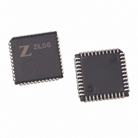
Z8F1601VN020SC Zilog, Z8F1601VN020SC Datasheet - Page 5

Z8F1601VN020SC
Manufacturer Part Number
Z8F1601VN020SC
Description
IC ENCORE MCU FLASH 16K 44-PLCC
Manufacturer
Zilog
Series
Encore!®r
Specifications of Z8F1601VN020SC
Core Processor
Z8
Core Size
8-Bit
Speed
20MHz
Connectivity
I²C, IrDA, SPI, UART/USART
Peripherals
Brown-out Detect/Reset, DMA, POR, PWM, WDT
Number Of I /o
31
Program Memory Size
16KB (16K x 8)
Program Memory Type
FLASH
Ram Size
2K x 8
Voltage - Supply (vcc/vdd)
3 V ~ 3.6 V
Data Converters
A/D 8x10b
Oscillator Type
Internal
Operating Temperature
0°C ~ 70°C
Package / Case
44-LCC (J-Lead)
Lead Free Status / RoHS Status
Contains lead / RoHS non-compliant
Eeprom Size
-
Other names
269-3129
Available stocks
Company
Part Number
Manufacturer
Quantity
Price
Table 1. Z8F640x, Z8F480x, Z8F320x, Z8F240x, Z8F160x Errata for Devices with Date
UP004207-0308
Sl
No
13
14
15
16
17
Summary
With the SPI
configured for multi-
master operation, an
occurrence of multi-
master collision will
not be detected.
The UART Receiver
and Transmitter
incorrectly test for
the setting of the
Parity Enable bit
when in Multiproces-
sor (MP) mode.
Data written to the
I
cannot be read
back.
Execution of a soft-
ware TRAP instruc-
tion may
erroneously clear
pending interrupts.
Driving the GPIO
port pins with a high-
impedance source
may result in logic
errors.
2
C Data register
Codes 0239 and Later (Continued)
Errata to Z8F640x, Z8F480x, Z8F320x, Z8F240x, Z8F160x (Z8 Encore!
Description
With the SPI configured for multi-master operation, a multi-master collision,
should it occur, will not be detected by the Z8 Encore!’s SPI device.
Workaround
A GPIO pin, configured as an input with interrupt on a falling edge, could
potentially be used to detect multi-master collisions. If the interrupt occurs with
the SPI configured as a Master, the user software could determine that a multi-
master collision has likely occurred.
The UART Receiver and Transmitter incorrectly test for the setting of the
Parity Enable (PEN) bit when in MP mode. The UART is not supposed to use
parity when the MP bit is enabled.
Workaround
When operating in MP mode, the user code should disable parity by clearing
the PEN bit in the UART Control 0 register.
Data written to the I
This is unlikely to affect user operation at all.
Workaround
None. Generally, the user code does not need to read back the data that was
written to the I
If an interrupt is pending and a software TRAP or an illegal instruction TRAP is
executed, the highest priority pending interrupt will be erroneously cleared.
This causes interrupts to be lost.
Workaround
Do not execute a software TRAP instruction.
When configured as inputs, the GPIO pins source high (50+ µA) current when
the input voltage on the pin is near mid-range. If a high impedance device is
used to drive the input, this can result in logic errors due to the resistive divider
effect of the current source and the external impedance.
Workaround
Do not drive the GPIO port input pins with high-impedance drivers (greater
than approximately 20 kΩ).
2
C Data register for transmission.
2
C Data register for transmission cannot be read back.
Page 5 of 15
®
)


