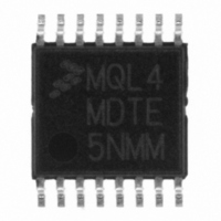
MC908QL4MDTE Freescale Semiconductor, MC908QL4MDTE Datasheet - Page 167

MC908QL4MDTE
Manufacturer Part Number
MC908QL4MDTE
Description
IC MCU 8BIT 4K FLASH 16-TSSOP
Manufacturer
Freescale Semiconductor
Series
HC08r
Datasheet
1.MC908QL3VDTE.pdf
(226 pages)
Specifications of MC908QL4MDTE
Core Processor
HC08
Core Size
8-Bit
Speed
8MHz
Connectivity
LIN (Local Interconnect Network)
Peripherals
LVD, POR, PWM
Number Of I /o
13
Program Memory Size
4KB (4K x 8)
Program Memory Type
FLASH
Ram Size
128 x 8
Voltage - Supply (vcc/vdd)
3 V ~ 5.5 V
Data Converters
A/D 6x10b
Oscillator Type
Internal
Operating Temperature
-40°C ~ 125°C
Package / Case
16-TSSOP
Lead Free Status / RoHS Status
Lead free / RoHS Compliant
Eeprom Size
-
- Current page: 167 of 226
- Download datasheet (3Mb)
Figure 14-22
incorrect value of 30 SLIC clocks for the length of one bit time, and a filter prescaler of 1. This makes little
difference in the receive sampling of this particular bit, as the sample point is still within the bit and the
digital filter will catch any noise pulses shorter than 16 filter clocks long.The ideal value of SLCBT would
be 35 SLIC clocks, but the closest available value is 34, placing the sample point at 17 SLIC clocks into
the bit.
The error in the bit time value chosen by the user in the above example will grow throughout the byte, as
the sample point for the next bit will be only 30 SLIC clock cycles later (1 full bit time at this bit rate setting).
The SLIC resynchronizes upon every falling edge received. In a 0x00 data byte, however, there are no
falling edges after the beginning of the start bit. This means that the accumulated error of the sampling
point over the data byte with these settings could be as high as 30 SLIC clock cycles (10 bits x {2 SLIC
clocks due to user error + 1 SLIC clock resolution error}) placing it at the boundary between the last bit
and the stop bit. This could result in missampling and missing a byte framing error on the last bit on high
speed communications when the SLCBT count is relatively low. A properly chosen SLCBT value would
result in a maximum error of 10 SLIC clock counts over a given byte. This is less than one filter delay time,
and will not cause missampling of any of the bits in that byte. At the falling edge of the next start bit, the
SLIC will resynchronize and any accumulated sampling error returns to 0. The sampling error becomes
even less significant at lower speeds, when higher values of SLCBT are used to define a bit time, as the
worst case bit time resolution error is still only one SLIC clock per bit (or maximum of 10 SLIC clocks per
byte).
Freescale Semiconductor
This example assumes a SLCBT value of 30 (0x1E).
Transmitted bits will be sent out as 30 SLIC clock cycles long.
The proper closest SLCBT setting would be 34 (0x22),
which gives the ideal sample point of 17 SLIC clocks and
transmitted bits are 34 SLIC clocks long.
(³1 PRESCALE)
(³1 PRESCALE)
FILTER CLOCK
UNFILTERED
SLIC CLOCK
FILTERED
RX DATA
RX DATA
COUNTING DOWN
FILTER BEGINS
shows an example of this error. In this example, the user has additionally chosen an
Figure 14-22. BTM Mode Receive Byte Sampling Example
16 FILTER CLOCKS
(³1 PRESCALE)
AND TOGGLES FILTER OUTPUT
FILTER REACHES 0X0
MC68HC908QL4 Data Sheet, Rev. 8
(1/2 OF SLCBT VALUE)
15 SLIC CLOCKS
(BASED ON SLCBT VALUE)
SLIC SAMPLE POINT
FILTER BEGINS
COUNTING UP
(ACTUAL FILTERED BIT LENGTH)
IDEAL SLIC SAMPLE POINT (17 SLIC CLOCKS)
Initialization/Application Information
35 SLIC CLOCKS
16 FILTER CLOCKS
(³1 PRESCALE)
AND TOGGLES FILTER OUTPUT
FILTER REACHES 0XF
167
Related parts for MC908QL4MDTE
Image
Part Number
Description
Manufacturer
Datasheet
Request
R

Part Number:
Description:
M68HC08 Microcontrollers
Manufacturer:
FREESCALE [Freescale Semiconductor, Inc]
Datasheet:
Part Number:
Description:
Manufacturer:
Freescale Semiconductor, Inc
Datasheet:
Part Number:
Description:
Manufacturer:
Freescale Semiconductor, Inc
Datasheet:
Part Number:
Description:
Manufacturer:
Freescale Semiconductor, Inc
Datasheet:
Part Number:
Description:
Manufacturer:
Freescale Semiconductor, Inc
Datasheet:
Part Number:
Description:
Manufacturer:
Freescale Semiconductor, Inc
Datasheet:
Part Number:
Description:
Manufacturer:
Freescale Semiconductor, Inc
Datasheet:
Part Number:
Description:
Manufacturer:
Freescale Semiconductor, Inc
Datasheet:
Part Number:
Description:
Manufacturer:
Freescale Semiconductor, Inc
Datasheet:
Part Number:
Description:
Manufacturer:
Freescale Semiconductor, Inc
Datasheet:
Part Number:
Description:
Manufacturer:
Freescale Semiconductor, Inc
Datasheet:
Part Number:
Description:
Manufacturer:
Freescale Semiconductor, Inc
Datasheet:
Part Number:
Description:
Manufacturer:
Freescale Semiconductor, Inc
Datasheet:
Part Number:
Description:
Manufacturer:
Freescale Semiconductor, Inc
Datasheet:
Part Number:
Description:
Manufacturer:
Freescale Semiconductor, Inc
Datasheet:


