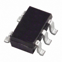
AD8061ARTZ-REEL7 Analog Devices Inc, AD8061ARTZ-REEL7 Datasheet - Page 18

AD8061ARTZ-REEL7
Manufacturer Part Number
AD8061ARTZ-REEL7
Description
IC OPAMP VF R-R LP 50MA SOT23-5
Manufacturer
Analog Devices Inc
Datasheet
1.AD8061ARTZ-REEL7.pdf
(20 pages)
Specifications of AD8061ARTZ-REEL7
Slew Rate
650 V/µs
Amplifier Type
Voltage Feedback
Number Of Circuits
1
Output Type
Rail-to-Rail
-3db Bandwidth
320MHz
Current - Input Bias
3.5µA
Voltage - Input Offset
1000µV
Current - Supply
6.8mA
Current - Output / Channel
50mA
Voltage - Supply, Single/dual (±)
2.7 V ~ 8 V, ±1.35 V ~ 4 V
Operating Temperature
-40°C ~ 85°C
Mounting Type
Surface Mount
Package / Case
SOT-23-5, SC-74A, SOT-25
Op Amp Type
Voltage Feedback
No. Of Amplifiers
1
Bandwidth
320MHz
Supply Voltage Range
2.7V To 8V
Amplifier Case Style
SOT-23
No. Of Pins
5
Rail/rail I/o Type
Rail to Rail Output
Number Of Elements
1
Common Mode Rejection Ratio
62dB
Input Offset Voltage
6@5VmV
Input Bias Current
9uA
Single Supply Voltage (typ)
5V
Dual Supply Voltage (typ)
Not RequiredV
Power Dissipation
500mW
Voltage Gain In Db
90dB
Power Supply Rejection Ratio
72dB
Power Supply Requirement
Single
Shut Down Feature
No
Single Supply Voltage (min)
2.7V
Single Supply Voltage (max)
8V
Dual Supply Voltage (min)
Not RequiredV
Dual Supply Voltage (max)
Not RequiredV
Operating Temp Range
-40C to 85C
Operating Temperature Classification
Industrial
Mounting
Surface Mount
Pin Count
5
Package Type
SOT-23
Lead Free Status / RoHS Status
Lead free / RoHS Compliant
Gain Bandwidth Product
-
Lead Free Status / Rohs Status
Compliant
Other names
AD8061ARTZ-REEL7
Available stocks
Company
Part Number
Manufacturer
Quantity
Price
Company:
Part Number:
AD8061ARTZ-REEL7
Manufacturer:
AD
Quantity:
3 000
Part Number:
AD8061ARTZ-REEL7
Manufacturer:
ADI/亚德诺
Quantity:
20 000
AD8061/AD8062/AD8063
MULTIPLEXER
The AD8063 has a disable pin used to power down the ampli-
fier to save power or to create a mux circuit. If two (or more)
AD8063 outputs are connected together, and only one is enabled,
then only the signal of the enabled amplifier will appear at the
output. This configuration is used to select from various input
signal sources. Additionally, the same input signal is applied to
different gain stages, or differently tuned filters, to make a gain-
step amplifier or a selectable frequency amplifier.
Figure 56 shows a schematic of two AD8063 devices used to
create a mux that selects between two inputs. One of these is a
1 V p-p, 3 MHz sine wave; the other is a 2 V p-p, 1 MHz sine wave.
1V p-p
3MHz
2V p-p
1MHz
BASE
BASE
SELECT
TIME
OUT
TIME
Figure 56. Two-to-One Multiplexer Using Two AD8063s
IN
1kΩ
1kΩ
49.9Ω
49.9Ω
AD8063
AD8063
+4V
–4V
+4V
–4V
0.1µF
0.1µF
0.1µF
0.1µF
HCO4
1
1
1kΩ
1kΩ
10µF
10µF
10µF
10µF
49.9Ω
49.9Ω
V
Rev. G | Page 18 of 20
OUT
The select signal and the output waveforms for this circuit are
shown in Figure 57. For synchronization clarity, two different
frequency synthesizers, whose time bases are locked to each
other, generate the signals.
OUTPUT
SELECT
Figure 57. AD8063 Mux Output
1V
2µs
2V


