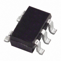
AD8061ARTZ-REEL7 Analog Devices Inc, AD8061ARTZ-REEL7 Datasheet - Page 2

AD8061ARTZ-REEL7
Manufacturer Part Number
AD8061ARTZ-REEL7
Description
IC OPAMP VF R-R LP 50MA SOT23-5
Manufacturer
Analog Devices Inc
Datasheet
1.AD8061ARTZ-REEL7.pdf
(20 pages)
Specifications of AD8061ARTZ-REEL7
Slew Rate
650 V/µs
Amplifier Type
Voltage Feedback
Number Of Circuits
1
Output Type
Rail-to-Rail
-3db Bandwidth
320MHz
Current - Input Bias
3.5µA
Voltage - Input Offset
1000µV
Current - Supply
6.8mA
Current - Output / Channel
50mA
Voltage - Supply, Single/dual (±)
2.7 V ~ 8 V, ±1.35 V ~ 4 V
Operating Temperature
-40°C ~ 85°C
Mounting Type
Surface Mount
Package / Case
SOT-23-5, SC-74A, SOT-25
Op Amp Type
Voltage Feedback
No. Of Amplifiers
1
Bandwidth
320MHz
Supply Voltage Range
2.7V To 8V
Amplifier Case Style
SOT-23
No. Of Pins
5
Rail/rail I/o Type
Rail to Rail Output
Number Of Elements
1
Common Mode Rejection Ratio
62dB
Input Offset Voltage
6@5VmV
Input Bias Current
9uA
Single Supply Voltage (typ)
5V
Dual Supply Voltage (typ)
Not RequiredV
Power Dissipation
500mW
Voltage Gain In Db
90dB
Power Supply Rejection Ratio
72dB
Power Supply Requirement
Single
Shut Down Feature
No
Single Supply Voltage (min)
2.7V
Single Supply Voltage (max)
8V
Dual Supply Voltage (min)
Not RequiredV
Dual Supply Voltage (max)
Not RequiredV
Operating Temp Range
-40C to 85C
Operating Temperature Classification
Industrial
Mounting
Surface Mount
Pin Count
5
Package Type
SOT-23
Lead Free Status / RoHS Status
Lead free / RoHS Compliant
Gain Bandwidth Product
-
Lead Free Status / Rohs Status
Compliant
Other names
AD8061ARTZ-REEL7
Available stocks
Company
Part Number
Manufacturer
Quantity
Price
Company:
Part Number:
AD8061ARTZ-REEL7
Manufacturer:
AD
Quantity:
3 000
Part Number:
AD8061ARTZ-REEL7
Manufacturer:
ADI/亚德诺
Quantity:
20 000
AD8061/AD8062/AD8063
TABLE OF CONTENTS
Features .............................................................................................. 1
Applications ....................................................................................... 1
Connection Diagrams ...................................................................... 1
General Description ......................................................................... 1
Revision History ............................................................................... 2
Specifications ..................................................................................... 3
Absolute Maximum Ratings ............................................................ 6
Typical Performance Characteristics ............................................. 7
Circuit Description ......................................................................... 14
REVISION HISTORY
2/10—Rev. F to Rev. G
Changes to Table 4 ............................................................................ 6
11/09—Rev. E to Rev. F
Changed Input Common-Mode Voltage Range Parameter........ 4
Updated Outline Dimensions ....................................................... 19
10/07—Rev. D to Rev. E
Changes to Applications .................................................................. 1
Updated Outline Dimensions ....................................................... 19
12/05—Rev. C to Rev. D
Updated Format .................................................................. Universal
Change to Features and General Description ............................... 1
Updated Outline Dimensions ....................................................... 19
Changes to Ordering Guide .......................................................... 20
5/01—Rev. B to Rev. C
Replaced TPC 9 with new graph .................................................... 7
11/00—Rev. A to Rev. B
2/00—Rev. 0 to Rev. A
11/99—Revision 0: Initial Version
Maximum Power Dissipation ..................................................... 6
ESD Caution .................................................................................. 6
Rev. G | Page 2 of 20
Applications Information .............................................................. 17
Outline Dimensions ....................................................................... 19
Headroom Considerations ........................................................ 14
Overload Behavior and Recovery ............................................ 15
Capacitive Load Drive ............................................................... 16
Disable Operation ...................................................................... 16
Board Layout Considerations ................................................... 16
Single-Supply Sync Stripper ...................................................... 17
RGB Amplifier ............................................................................ 17
Multiplexer .................................................................................. 18
Ordering Guide .......................................................................... 20


