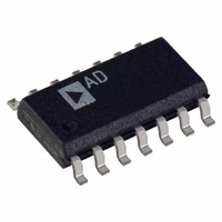
AD8279ARZ Analog Devices Inc, AD8279ARZ Datasheet - Page 19

AD8279ARZ
Manufacturer Part Number
AD8279ARZ
Description
IC AMP DIFF LP 14SOIC
Manufacturer
Analog Devices Inc
Datasheet
1.AD8279ARZ.pdf
(24 pages)
Specifications of AD8279ARZ
Amplifier Type
Differential
Number Of Circuits
2
Output Type
Rail-to-Rail
Slew Rate
1.4 V/µs
Gain Bandwidth Product
1MHz
Voltage - Input Offset
50µV
Current - Supply
300µA
Current - Output / Channel
15mA
Voltage - Supply, Single/dual (±)
2 V ~ 36 V, ±2 V ~ 18 V
Operating Temperature
-40°C ~ 85°C
Mounting Type
Surface Mount
Package / Case
14-SOIC (3.9mm Width), 14-SOL
No. Of Amplifiers
2
Input Offset Voltage
500µV
Bandwidth
1MHz
Supply Voltage Range
2V To 36V
Supply Current
200µA
Amplifier Case Style
SOIC
No. Of Pins
14
Rohs Compliant
Yes
Lead Free Status / RoHS Status
Lead free / RoHS Compliant
-3db Bandwidth
-
Current - Input Bias
-
Available stocks
Company
Part Number
Manufacturer
Quantity
Price
Company:
Part Number:
AD8279ARZ
Manufacturer:
Vishay
Quantity:
540
Part Number:
AD8279ARZ
Manufacturer:
ADI/亚德诺
Quantity:
20 000
The reference must be driven with a low impedance source to
maintain the internal resistor ratio. An example using the low
power, low noise
DIFFERENTIAL OUTPUT
The two difference amplifiers of the AD8279 can be configured
to provide a differential output, as shown in Figure 59. This
differential output configuration is suitable for various applications,
such as strain gage excitation and single-ended-to-differential
conversion. The differential output voltage has a gain twice that
of a single AD8279 channel, as shown in the following equation:
If the AD8279 amplifiers are each configured for G = ½, the
differential gain is 1×; if the AD8279 amplifiers are each
configured for G = 2, the differential gain is 4×.
V
DIFF_OUT
Figure 59. AD8279 Differential Output G = 4 Configuration
–IN
+IN
V
= V
INCORRECT
AD8278
OP1177
Figure 58. Driving the Reference Pin
+OUT
REF
12
14
10
8
− V
20kΩ
20kΩ
20kΩ
20kΩ
−OUT
as a reference is shown in Figure 58.
+VS
–VS
= 2 × G
11
4
V
AD8279
40kΩ
40kΩ
40kΩ
40kΩ
+
OP1177
–
CORRECT
AD8279
AD8278
13
2
3
6
9
5
× ( V
REF
IN+
+OUT
–OUT
– V
IN−
)
Rev. C | Page 19 of 24
INSTRUMENTATION AMPLIFIER
The AD8278 and AD8279 can be used as building blocks for a
low power, low cost instrumentation amplifier. An instrumentation
amplifier provides high impedance inputs and delivers high
common-mode rejection. Combining the AD8278 with an Analog
Devices, Inc., low power amplifier (see Table 11) creates a precise,
power efficient voltage measurement solution suitable for power
critical systems.
Table 11. Low Power Op Amps
Op Amp (A1, A2)
AD8506
AD8607
AD8617
AD8667
It is preferable to use dual op amps for the high impedance inputs
because they have better matched performance and track each
other over temperature. The AD8278 and AD8279 difference
amplifiers cancel out common-mode errors from the input op
amps, if they track each other. The differential gain accuracy of
the in-amp is proportional to how well the input feedback
resistors (R
increases as the differential gain is increased (1 + 2R
higher gain also reduces the common-mode voltage range.
Refer to A Designer’s Guide to Instrumentation Amplifiers for
more design ideas and considerations at www.analog.com,
under Technical Documentation.
–IN
+IN
R
Figure 60. Low Power Precision Instrumentation Amplifier
G
F
) match each other. The CMRR of the in-amp
A1
A2
R
R
F
F
Features
Dual micropower op amp
Precision dual micropower op amp
Low cost CMOS micropower op amp
Dual precision CMOS micropower op amp
V
OUT
20kΩ
20kΩ
40kΩ
= (1 + 2R
REF
AD8278/
AD8279
AD8278/AD8279
F
/R
40kΩ
G
) (V
IN+
– V
IN–
) × 2
F
V
/R
OUT
G
), but a


