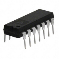
AD841JNZ Analog Devices Inc, AD841JNZ Datasheet - Page 3

AD841JNZ
Manufacturer Part Number
AD841JNZ
Description
IC OPAMP GP 40MHZ 50MA 14DIP
Manufacturer
Analog Devices Inc
Datasheet
1.AD841JNZ.pdf
(8 pages)
Specifications of AD841JNZ
Slew Rate
300 V/µs
Amplifier Type
General Purpose
Number Of Circuits
1
Gain Bandwidth Product
40MHz
Current - Input Bias
3.5µA
Voltage - Input Offset
800µV
Current - Supply
11mA
Current - Output / Channel
50mA
Voltage - Supply, Single/dual (±)
±5 V ~ 18 V
Operating Temperature
0°C ~ 75°C
Mounting Type
Through Hole
Package / Case
14-DIP (0.300", 7.62mm)
Op Amp Type
Unity Gain Stable
No. Of Amplifiers
1
Bandwidth
40MHz
Supply Voltage Range
± 5V To ± 18V
Amplifier Case Style
DIP
No. Of Pins
14
Lead Free Status / RoHS Status
Lead free / RoHS Compliant
Output Type
-
-3db Bandwidth
-
Lead Free Status / RoHS Status
Lead free / RoHS Compliant, Lead free / RoHS Compliant
Available stocks
Company
Part Number
Manufacturer
Quantity
Price
REV. B
ABSOLUTE MAXIMUM RATINGS
Supply Voltage . . . . . . . . . . . . . . . . . . . . . . . . . . . . . . . .
Internal Power Dissipation
Input Voltage . . . . . . . . . . . . . . . . . . . . . . . . . . . . . . . . . . . Vs
Differential Input Voltage . . . . . . . . . . . . . . . . . . . . . . . .
Storage Temperature Range
Junction Temperature . . . . . . . . . . . . . . . . . . . . . . . . . +175 C
Lead Temperature Range (Soldering 60 sec) . . . . . . . . +300 C
TO-8 (H) . . . . . . . . . . . . . . . . . . . . . . . . . . . . . . . . . . 1.4 W
Plastic (N) . . . . . . . . . . . . . . . . . . . . . . . . . . . . . . . . . 1.5 W
Cerdip (Q) . . . . . . . . . . . . . . . . . . . . . . . . . . . . . . . . . 1.3 W
Q, H, E . . . . . . . . . . . . . . . . . . . . . . . . . . –65 C to +150 C
N . . . . . . . . . . . . . . . . . . . . . . . . . . . . . . . .–65 C to +125 C
2
1
METALIZATION PHOTOGRAPH
Dimensions shown in inches and (mm).
Contact factory for latest dimensions.
18 V
6 V
–3–
NOTES
1
2
Stresses above those listed under “Absolute Maximum Ratings” may cause
permanent damage to the device. This is a stress rating only, and functional
operation of the device at these or any other conditions above those indicated in
the operational section of this specification is not implied. Exposure to absolute
maximum rating conditions for extended periods may affect device reliability.
Maximum internal power dissipation is specified so that T
+175 C at an ambient temperature of +25 C.
LCC Package
Thermal Characteristics:
Cerdip Package 35 C/W 110 C/W
TO-8 Package
Plastic Package 30 C/W 100 C/W
30 C/W 100 C/W
35 C/W 150 C/W
JC
JA
38 C/W Recommended Heat Sink:
37 C/W Aavid Engineering© #602B
SA
AD841
J
does not exceed


