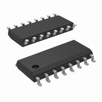
LM13700MX/NOPB National Semiconductor, LM13700MX/NOPB Datasheet - Page 2

LM13700MX/NOPB
Manufacturer Part Number
LM13700MX/NOPB
Description
IC AMP DUAL OP TRANSCOND 16-SOIC
Manufacturer
National Semiconductor
Datasheet
1.LM13700NNOPB.pdf
(26 pages)
Specifications of LM13700MX/NOPB
Amplifier Type
Transconductance
Number Of Circuits
2
Output Type
Push-Pull
Slew Rate
50 V/µs
Gain Bandwidth Product
2MHz
Current - Input Bias
1µA
Voltage - Input Offset
300µV
Current - Supply
2.6mA
Current - Output / Channel
650µA
Voltage - Supply, Single/dual (±)
10 V ~ 36 V, ±5 V ~ 18 V
Operating Temperature
0°C ~ 70°C
Mounting Type
Surface Mount
Package / Case
16-SOIC (3.9mm Width)
Lead Free Status / RoHS Status
Lead free / RoHS Compliant
-3db Bandwidth
-
Other names
*LM13700MX
*LM13700MX/NOPB
LM13700MX
*LM13700MX/NOPB
LM13700MX
Available stocks
Company
Part Number
Manufacturer
Quantity
Price
Part Number:
LM13700MX/NOPB
Manufacturer:
TI/德州仪器
Quantity:
20 000
www.national.com
Input Offset Voltage (V
V
Input Offset Change
Input Offset Current
Input Bias Current
Forward
Transconductance (g
g
Peak Output Current
Peak Output Voltage
Supply Current
V
CMRR
Common Mode Range
Crosstalk
Differential Input Current
Leakage Current
Input Resistance
Open Loop Bandwidth
Slew Rate
Buffer Input Current
Peak Buffer Output Voltage
Absolute Maximum Ratings
If Military/Aerospace specified devices are required,
please contact the National Semiconductor Sales Office/
Distributors for availability and specifications.
Electrical Characteristics
Note 1: “Absolute Maximum Ratings” indicate limits beyond which damage to the device may occur. Operating Ratings indicate conditions for which the device is
functional, but do not guarantee specific performance limits.
Note 2: For operation at ambient temperatures above 25˚C, the device must be derated based on a 150˚C maximum junction temperature and a thermal resistance,
junction to ambient, as follows: LM13700N, 90˚C/W; LM13700M, 110˚C/W.
Note 3: Buffer output current should be limited so as to not exceed package dissipation.
Supply Voltage
Power Dissipation (Note 2) T
Differential Input Voltage
Diode Bias Current (I
Amplifier Bias Current (I
Output Short Circuit Duration
m
OS
OS
Positive
Negative
Positive
Negative
LM13700
LM13700N
Tracking
Including Diodes
Sensitivity
Parameter
m
D
)
OS
)
ABC
)
)
A
= 25˚C
Over Specified Temperature Range
I
Diode Bias Current (I
5 µA ≤ I
Over Specified Temperature Range
Over Specified Temperature Range
R
R
R
R
R
I
∆V
∆V
Referred to Input (Note 5)
20 Hz
I
I
Unity Gain Compensated
(Note 5)
(Note 5)
ABC
ABC
ABC
ABC
L
L
L
L
L
OS
OS
= 0, I
= 0, I
= 0, Over Specified Temp Range
=
=
= 5 µA
= 500 µA, Both Channels
= 0, Input =
= 0 (Refer to Test Circuit)
/∆V
/∆V
∞
∞
<
36 V
, 5 µA ≤ I
, 5 µA ≤ I
(Note 4)
ABC
ABC
ABC
+
−
f
<
DC
(Note 1)
Continuous
≤ 500 µA
= 5 µA
= 500 µA
20 kHz
or
570 mW
Conditions
ABC
ABC
±
±
2 mA
2 mA
±
4V
18V
5V
≤ 500 µA
≤ 500 µA
D
) = 500 µA
2
Buffer Output Current (Note 3)
Operating Temperature Range
DC Input Voltage
Storage Temperature Range
Soldering Information
LM13700N
Dual-In-Line Package
Small Outline Package
Soldering (10 sec.)
Vapor Phase (60 sec.)
Infrared (15 sec.)
6700
5400
Min
350
300
+12
−12
±
80
10
10
12
LM13700
+14.2
−14.4
±
9600
0.02
Typ
500
110
100
0.4
0.3
0.5
0.1
0.1
0.4
0.3
2.6
0.2
0.5
13.5
20
20
26
50
1
5
2
13000
−65˚C to +150˚C
Max
650
150
150
100
100
0.6
4
4
5
3
5
8
2
0˚C to +70˚C
+V
S
20 mA
to −V
260˚C
215˚C
220˚C
Units
µmho
µV/V
µV/V
MHz
V/µs
mV
mV
mV
mA
µA
µA
dB
µA
dB
dB
nA
nA
kΩ
µA
V
V
V
V
S


