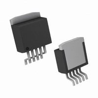
LP3891ES-1.2/NOPB National Semiconductor, LP3891ES-1.2/NOPB Datasheet - Page 9

LP3891ES-1.2/NOPB
Manufacturer Part Number
LP3891ES-1.2/NOPB
Description
IC REG LDO 0.8A 1.2V TO-263-5
Manufacturer
National Semiconductor
Datasheet
1.LP3891ES-1.2NOPB.pdf
(11 pages)
Specifications of LP3891ES-1.2/NOPB
Regulator Topology
Positive Fixed
Voltage - Output
1.2V
Voltage - Input
Up to 5.5V
Voltage - Dropout (typical)
0.1V @ 800mA
Number Of Regulators
1
Current - Output
800mA
Operating Temperature
-40°C ~ 125°C
Mounting Type
Surface Mount
Package / Case
TO-263-5, D²Pak (5 leads + Tab), TO-263BA
Lead Free Status / RoHS Status
Lead free / RoHS Compliant
Current - Limit (min)
-
Other names
*LP3891ES-1.2
*LP3891ES-1.2/NOPB
LP3891ES-1.2
*LP3891ES-1.2/NOPB
LP3891ES-1.2
Application Hints
HEATSINKING TO-263 PACKAGE
The TO-263 package uses the copper plane on the PCB as
a heatsink. The tab of these packages are soldered to the
copper plane for heat sinking. The graph below shows a
curve for the θ
sizes, using a typical PCB with 1 ounce copper and no solder
mask over the copper area for heat sinking.
As shown in the graph below, increasing the copper area
beyond 1 square inch produces very little improvement. The
minimum value for θ
PCB is 32˚C/W.
Figure 2 shows the maximum allowable power dissipation
for TO-263 packages for different ambient temperatures,
assuming θ
ture is 125˚C.
FIGURE 1. θ
FIGURE 2. Maximum power dissipation vs ambient
JA
temperature for TO-263 package
JA
is 35˚C/W and the maximum junction tempera-
JA
of TO-263 package for different copper area
vs Copper (1 Ounce) Area for TO-263
JA
for the TO-263 package mounted to a
package
(Continued)
20069525
20069526
9
HEATSINKING PSOP PACKAGE
Heatsinking for the PSOP-8 package is accomplished by
allowing heat to flow through the ground slug on the bottom
of the package into the copper on the PC board. The heat
slug must be soldered down to a copper plane to get good
heat transfer. It can also be connected through vias to inter-
nal copper planes. Since the heat slug is at ground potential,
traces must not be routed under it which are not at ground
potential. Under all possible conditions, the junction tem-
perature must be within the range specified under operating
conditions.
Figure 3 shows a curve for the θ
different copper area sizes using a typical PCB with one
ounce copper in still air.
FIGURE 3. θ
JA
vs. Copper (1 ounce) Area for PSOP
Package
JA
of the PSOP package for
20069554
www.national.com


