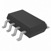
LT3060ITS8#TRMPBF Linear Technology, LT3060ITS8#TRMPBF Datasheet - Page 18

LT3060ITS8#TRMPBF
Manufacturer Part Number
LT3060ITS8#TRMPBF
Description
IC REG LDO ADJ .1A 8TSOT
Manufacturer
Linear Technology
Datasheet
1.LT3060EDCTRMPBF.pdf
(26 pages)
Specifications of LT3060ITS8#TRMPBF
Regulator Topology
Positive Adjustable
Voltage - Output
0.6 ~ 44.5 V
Voltage - Input
1.6 ~ 45 V
Voltage - Dropout (typical)
0.3V @ 100mA
Number Of Regulators
1
Current - Output
100mA
Current - Limit (min)
110mA
Operating Temperature
-40°C ~ 125°C
Mounting Type
Surface Mount
Package / Case
TSOT-23-8, TSOT-8
Lead Free Status / RoHS Status
Lead free / RoHS Compliant
Available stocks
Company
Part Number
Manufacturer
Quantity
Price
applicaTions inForMaTion
LT3060 Series
During start-up, the internal reference soft-starts if a
reference bypass capacitor is present. Regulator start-
up time is directly proportional to the size of the bypass
capacitor, slowing to 6ms with a 10nF bypass capacitor
(See Start-up Time vs REF/BYP Capacitor in the Typical
Performance Characteristics section). The reference by-
pass capacitor is actively pulled low during shutdown to
reset the internal reference.
Start-up time is also affected by the use of a feedforward
capacitor. Start-up time is directly proportional to the size
of the feedforward capacitor and output voltage, and is
inversely proportional to the feedback resistor divider
current, slowing to 15ms with a 4.7nF feedforward ca-
pacitor and a 10µF output capacitor for an output voltage
set to 5V by a 5µA feedback resistor divider.
Output Capacitance
The LT3060 regulators are stable with a wide range of
output capacitors. The ESR of the output capacitor af-
fects stability, most notably with small capacitors. Use
a minimum output capacitor of 2.2µF with an ESR of 3Ω
or less to prevent oscillations. If a feedforward capacitor
is used with output voltages set for greater than 24V, use
a minimum output capacitor of 4.7µF. The LT3060 is a
micropower device and output load transient response is
a function of output capacitance. Larger values of output
capacitance decrease the peak deviations and provide
improved transient response for larger load current
18
Figure 4. Ceramic Capacitor DC Bias Characteristics
–100
–20
–40
–60
–80
20
0
0
2
4
DC BIAS VOLTAGE (V)
BOTH CAPACITORS ARE 16V,
1210 CASE SIZE, 10µF
6
8
Y5V
X5R
10
12
14
3060 F04
16
changes. Bypass capacitors, used to decouple individual
components powered by the LT3060, increase the effec-
tive output capacitor value. For applications with large
load current transients, a low ESR ceramic capacitor in
parallel with a bulk tantalum capacitor often provides an
optimally damped response.
Give extra consideration to the use of ceramic capacitors.
Manufacturers make ceramic capacitors with a variety of
dielectrics, each with different behavior across tempera-
ture and applied voltage. The most common dielectrics
are specified with EIA temperature characteristic codes
of Z5U, Y5V, X5R and X7R. The Z5U and Y5V dielectrics
provide high C-V products in a small package at low cost ,
but exhibit strong voltage and temperature coefficients, as
shown in Figures 4 and 5. When used with a 5V regulator,
a 16V 10µF Y5V capacitor can exhibit an effective value
as low as 1µF to 2µF for the DC bias voltage applied, and
over the operating temperature range. The X5R and X7R
dielectrics yield much more stable characteristics and
are more suitable for use as the output capacitor.
The X7R type works over a wider temperature range
and has better temperature stability, while the X5R is
less expensive and is available in higher values. Care
still must be exercised when using X5R and X7R ca-
pacitors; the X5R and X7R codes only specify operating
temperature range and maximum capacitance change
over temperature. Capacitance change due to DC bias
with X5R and X7R capacitors is better than Y5V and Z5U
Figure 5. Ceramic Capacitor Temperature Characteristics
–100
–20
–40
–60
–80
40
20
0
–50
BOTH CAPACITORS ARE 16V,
1210 CASE SIZE, 10µF
–25
0
TEMPERATURE (°C)
25
50
Y5V
75
X5R
100
3060 F05
125
3060fa


