LMS8117ADT-3.3/NOPB National Semiconductor, LMS8117ADT-3.3/NOPB Datasheet - Page 8
LMS8117ADT-3.3/NOPB
Manufacturer Part Number
LMS8117ADT-3.3/NOPB
Description
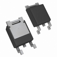
IC REGULATOR 1A LDO TO-252
Manufacturer
National Semiconductor
Type
Linearr
Datasheet
1.LMS8117AMPX-1.8NOPB.pdf
(16 pages)
Specifications of LMS8117ADT-3.3/NOPB
Regulator Topology
Positive Fixed
Voltage - Output
3.3V
Voltage - Input
Up to 15V
Voltage - Dropout (typical)
1.2V @ 1A
Number Of Regulators
1
Current - Output
1A
Current - Limit (min)
1A
Operating Temperature
0°C ~ 125°C
Mounting Type
Surface Mount
Package / Case
TO-252-2, DPak (2 Leads + Tab), TO-252AA, SC-63
Package
3TO-252
Function
LDO
Number Of Outputs
1
Input Voltage Range
15 to 2.5 V
Output Voltage
3.3 V
Maximum Output Current
1 A
Output Type
Fixed
Accuracy
±1 %
Typical Dropout Voltage @ Current
1.1@100mA|1.15@500mA|1.2@1A V
Polarity
Positive
Lead Free Status / RoHS Status
Lead free / RoHS Compliant
Other names
*LMS8117ADT-3.3
*LMS8117ADT-3.3/NOPB
LMS8117ADT-3.3
*LMS8117ADT-3.3/NOPB
LMS8117ADT-3.3
Available stocks
Company
Part Number
Manufacturer
Quantity
Price
Company:

Part Number:
LMS8117ADT-3.3/NOPB
Manufacturer:
TI
Quantity:
20 000


www.national.com
Application Note
When the adjustable regulator is used (Figure 3), the best
performance is obtained with the positive side of the resistor
R1 tied directly to the output terminal of the regulator rather
than near the load. This eliminates line drops from appearing
effectively in series with the reference and degrading regu-
lation. For example, a 5V regulator with 0.05Ω resistance
between the regulator and load will have a load regulation
due to line resistance of 0.05Ω x I
nected near the load, the effective line resistance will be
0.05Ω (1+R2/R1) or in this case, it is 4 times worse. In
addition, the ground side of the resistor R2 can be returned
near the ground of the load to provide remote ground sens-
ing and improve load regulation.
4.0 PROTECTION DIODES
Under normal operation, the LMS8117A regulators do not
need any protection diode. With the adjustable device, the
internal resistance between the adjust and output terminals
limits the current. No diode is needed to divert the current
around the regulator even with capacitor on the adjust ter-
minal. The adjust pin can take a transient signal of
respect to the output voltage without damaging the device.
When a output capacitor is connected to a regulator and the
input is shorted to ground, the output capacitor will discharge
into the output of the regulator. The discharge current de-
pends on the value of the capacitor, the output voltage of the
regulator, and rate of decrease of V
regulators, the internal diode between the output and input
pins can withstand microsecond surge currents of 10A to
20A. With an extremely large output capacitor (≥1000 µF),
and with input instantaneously shorted to ground, the regu-
lator could be damaged.
In this case, an external diode is recommended between the
output and input pins to protect the regulator, as shown in
Figure 4.
FIGURE 3. Best Load Regulation using Adjustable
Output Regulator
(Continued)
L
. If R1 (=125Ω) is con-
IN
. In the LMS8117A
±
25V with
10119619
8
5.0 HEATSINK REQUIREMENTS
When an integrated circuit operates with an appreciable
current, its junction temperature is elevated. It is important to
quantify its thermal limits in order to achieve acceptable
performance and reliability. This limit is determined by sum-
ming the individual parts consisting of a series of tempera-
ture rises from the semiconductor junction to the operating
environment. A one-dimensional steady-state model of con-
duction heat transfer is demonstrated in Figure 5. The heat
generated at the device junction flows through the die to the
die attach pad, through the lead frame to the surrounding
case material, to the printed circuit board, and eventually to
the ambient environment. Below is a list of variables that
may affect the thermal resistance and in turn the need for a
heatsink.
Leadframe Size & Material Mounting Pad Size,
No. of Conduction Pins
Die Size
Die Attach Material
Molding Compound Size
and Material
R
FIGURE 4. Regulator with Protection Diode
θJC
Variables)
(Component
Material, & Location
Placement of Mounting
Pad
PCB Size & Material
Traces Length & Width
Adjacent Heat Sources
Volume of Air
Ambient Temperatue
Shape of Mounting Pad
R
θCA
Variables)
(Application
10119615
Related parts for LMS8117ADT-3.3/NOPB
Image
Part Number
Description
Manufacturer
Datasheet
Request
R

Part Number:
Description:
IC,VOLT REGULATOR,FIXED,+3.3V,BIPOLAR,SIP,3PIN,PLASTIC
Manufacturer:
National Semiconductor

Part Number:
Description:
Linear Voltage Regulator IC
Manufacturer:
National Semiconductor
Datasheet:

Part Number:
Description:
1A Low-Dropout Linear Regulator
Manufacturer:
NSC [National Semiconductor]
Datasheet:

Part Number:
Description:
IC REGULATOR 1A LDO TO-252
Manufacturer:
National Semiconductor
Datasheet:
Part Number:
Description:
IC REG LINEAR LDO 1A 1.8V TO-252
Manufacturer:
National Semiconductor
Datasheet:
Part Number:
Description:
National Semiconductor [8-Bit D/A Converter]
Manufacturer:
National Semiconductor
Datasheet:
Part Number:
Description:
National Semiconductor [Media Coprocessor]
Manufacturer:
National Semiconductor
Datasheet:
Part Number:
Description:
Digitally Controlled Tone and Volume Circuit with Stereo Audio Power Amplifier, Microphone Preamp Stage and National 3D Sound
Manufacturer:
National Semiconductor
Datasheet:
Part Number:
Description:
Digitally Controlled Tone and Volume Circuit with Stereo Audio Power Amplifier, Microphone Preamp Stage and National 3D Sound
Manufacturer:
National Semiconductor
Datasheet:
Part Number:
Description:
AC97 Rev 2 Codec with Sample Rate Conversion and National 3D Sound
Manufacturer:
National Semiconductor
Part Number:
Description:
Manufacturer:
National Semiconductor
Datasheet:
Part Number:
Description:
Manufacturer:
National Semiconductor
Datasheet:
Part Number:
Description:
General Purpose, Low Voltage, Low Power, Rail-to-Rail Output Operational Amplifiers
Manufacturer:
National Semiconductor
Datasheet:
Part Number:
Description:
8-bit 20 MSPS flash A/D converter.
Manufacturer:
National Semiconductor
Datasheet: