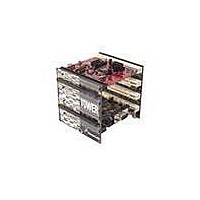
TWR-K60N512-KIT Freescale Semiconductor, TWR-K60N512-KIT Datasheet
TWR-K60N512-KIT
Specifications of TWR-K60N512-KIT


Related parts for TWR-K60N512-KIT

TWR-K60N512-KIT Summary of contents
Page 1
... TWR-K60N512 Tower Module Freescale Semiconductor Inc. User's Manual Rev. 1.0 ...
Page 2
... TWR-K60N512 and TWR-K60N512-KIT Overview ..................................................................... 4 1.1 Contents .................................................................................................................................................................................. 4 1.2 Features .................................................................................................................................................................................. 5 1.3 Getting Started ..................................................................................................................................................................... 6 1.4 Reference Documents ....................................................................................................................................................... 6 2 Hardware Description ........................................................................................................................... 6 2.1 K60N512 Microcontroller ............................................................................................................................................... 7 2.2 Clocking .................................................................................................................................................................................. 8 2.3 System Power ....................................................................................................................................................................... 8 2.3.1 RTC VBAT .............................................................................................................................................................................................. 8 2.4 Debug Interface ................................................................................................................................................................... 9 2.4.1 OSJTAG .................................................................................................................................................................................................... 9 2.4.2 Cortex Debug+ETM Connector ..................................................................................................................................................... 9 2.5 Infrared Port ...................................................................................................................................................................... 10 2.6 Accelerometer ................................................................................................................................................................... 10 2 ...
Page 3
... Figure 1. Freescale Tower System Overview .............................................................................................. 4 Figure 2. Callouts on front side of the TWR-K60N512 ................................................................................ 5 Figure 3. Callouts on back side of the TWR-K60N512 ................................................................................ 6 Figure 4. TWR-K60N512 Block Diagram ...................................................................................................... 7 Figure 5. Infrared Port Implementation ................................................................................................... 10 Table 1. Cortex Debug+ETM Connector Pinout .......................................................................................... 9 Table 2. General Purpose TWRPI socket pinout ....................................................................................... 11 Table 3. Touch TWRPI socket pinout ........................................................................................................ 12 Table 4 ...
Page 4
... ARM® Cortex™-M4 architecture with USB 2.0 full-speed OTG controller and 10/100 Mbps Ethernet MAC. The TWR-K60N512 is available as a stand-alone product kit (TWR-K60N512-KIT) with the Tower Elevator Modules (TWR-ELEV) and the Tower Serial Module (TWR-SER). The TWR-K60N512 can also be combined with other Freescale Tower peripheral modules to create development platforms for a wide variety of applications ...
Page 5
... The TWR-K60N512-KIT contains: TWR-K60N512 MCU module TWR-ELEV – Primary and Secondary Elevator Modules TWR-SER – Serial module including USB host/device/OTG, Ethernet, CAN, RS232 and RS485 1.2 Features Figure 2 and Figure 3 show the TWR-K60N512 with some of the key features called out. The following ...
Page 6
... Figure 3. Callouts on back side of the TWR-K60N512 1.3 Getting Started Follow the Quick Start Guide found printed in the TWR-K60N512 box or the interactive DVD for the list of recommended steps for getting started. There are also lab walk-through guides available on the tool support page for the TWR-K60N512: http://www.freescale.com/TWR-K60N512. ...
Page 7
... USB mini-AB connector. Figure 4 shows a block diagram of the TWR-K60N512. The following sections describe the hardware in more detail. 5.0V SDHC, I 5.0V OSJTAG JTAG, Power, SCI USB Mini-B Battery VBAT (RTC) Holder SDHC General Purpose ...
Page 8
... The EXTAL pin of the main external oscillator can also be driven directly from an external clock source. The TWR-K60N512 features a 50 MHz on-board clock oscillator as seen in sheet 4 of the schematics. However, when the K60 Ethernet MAC is operating in RMII mode, synchronization of the MCU input clock and the 50 MHz RMII transfer clock is important ...
Page 9
... VBAT. The TWR-K60N512 provides a battery holder for a coin cell battery that can be used as the VBAT supply. The holder can accept common 20mm diameter 3V lithium coin cell batteries (e.g. 2032, 2025). Refer to the description J9 in Table 5 “TWR-K60N512 Jumper Table” for more information. ...
Page 10
... TRACEDATA[3] Note: Many of the trace signals connected to the debug connector are also connected elsewhere on the TWR-K60N512. Refer to Table 6 “I/O Connectors and Pin Usage Table” and Table 7 “TWR-K60N512 Primary Connector Pinout” for more information. 2.5 Infrared Port An infrared transmit and receive interface is implemented as shown in Figure 5 below. The CMT_IRO pin directly drives an infrared diode ...
Page 11
... Touch Tower Plug-in (TWRPI) socket that can accept Touch TWRPI daughter cards that may feature keypads, rotary dials, sliders, etc. The pinout for the Touch TWRPI socket is defined in Table 3. Refer to Table 6 “I/O Connectors and Pin Usage Table” for the specific K60 pin connections to the Touch TWRPI socket. ...
Page 12
... Connector. The Tower peripheral module implementing the RMII PHY device should drive a 50 MHz clock on the CLKIN0 pin that is kept in phase with the clock supplied to the RMII PHY. The TWR-SER module that comes as part of the TWR-K60N512-KIT provides a 10/100 Ethernet PHY that can operate in either MII or RMII mode. By default the PHY is boot strapped to operate in MII mode ...
Page 13
... Connector, allowing the connection to external USB connectors or additional circuitry on a Tower peripheral module. The TWR-SER module included as part of the TWR-K60N512-KIT provides a USB OTG/Host/Device interface with a mini-AB USB connector. There are many configuration options that can be selected to evaluate different USB modes of operation. By default, the TWR-SER is configured for USB Device operation ...
Page 14
... Input/Output Connectors and Pin Usage Table The following table provides details on which K60N512 pins are using to communicate with the LEDs, switches, and other I/O interfaces onboard the TWR-K60N512. Note: Some port pins are used in multiple interfaces on-board and many are potentially connected to off-board resources via the Primary and Secondary Connectors ...
Page 15
... The TWR-K60N512 features two expansion card-edge connectors that interface to the Primary and Secondary Elevator boards in a Tower system. The Primary Connector (comprised of sides A and B) is utilized by the TWR-K60N512 while the Secondary Connector (comprised of sides C and D) only makes connections to the GND pins. Table 7 provides the pinout for the Primary Connector. ...
Page 16
... Table 7. TWR-K60N512 Primary Connector Pinout Side B Pin # Name B1 5V 5.0V Power B2 GND Ground B3 3.3V 3.3V Power B4 ELE_PS_SENSE Elevator Power Sense B5 GND Ground B6 GND Ground SDHC_CLK / SPI1_CLK PTE2 B7 SDHC_D3 / SPI1_CS1_b B8 SDHC_D3 / SPI1_CS0_b PTE4 B9 SDHC_CMD / SPI1_MOSI PTE1 B10 SDHC_D0 / SPI1_MISO PTE3 B11 ETH_COL ...
Page 17
... EBI_D3 PTC12 B77 EBI_D2 PTC13 B78 EBI_D1 PTC14 B79 EBI_D0 PTC15 B80 B81 GND Ground B82 3.3V 3.3V Power TWR-K60N512 Tower Module User's Manual Pin # Usage Name A47 VREFA1 A48 VREFA2 A49 GND A50 GPIO14 A51 GPIO15 A52 GPIO16 A53 GPIO17 ...