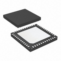
ATA5824-PLQW Atmel, ATA5824-PLQW Datasheet - Page 58

ATA5824-PLQW
Manufacturer Part Number
ATA5824-PLQW
Description
IC TXRX UHF ASK/FSK 48QFN
Manufacturer
Atmel
Datasheet
1.ATA5824-PLQW.pdf
(98 pages)
Specifications of ATA5824-PLQW
Frequency
433 ~ 435MHz; 866 ~ 870MHz
Data Rate - Maximum
20kbps
Modulation Or Protocol
ASK, FSK
Applications
RKE, TPM, Security Systems
Power - Output
10dBm
Sensitivity
-116dBm
Voltage - Supply
2.15 V ~ 3.6 V or 4.4 V ~ 5.25 V
Current - Receiving
10.5mA
Current - Transmitting
10.5mA
Data Interface
PCB, Surface Mount
Antenna Connector
PCB, Surface Mount
Operating Temperature
-40°C ~ 105°C
Package / Case
48-VQFN Exposed Pad, 48-HVQFN, 48-SQFN, 48-DHVQFN
Lead Free Status / RoHS Status
Lead free / RoHS Compliant
Memory Size
-
Available stocks
Company
Part Number
Manufacturer
Quantity
Price
Company:
Part Number:
ATA5824-PLQW
Manufacturer:
ATMEL
Quantity:
3 500
Part Number:
ATA5824-PLQW
Manufacturer:
ATMEL/爱特梅尔
Quantity:
20 000
14.1.7
Figure 14-7. Receiving Mode (TMODE = 1)
58
ATA5823/ATA5824
Receiving Mode
SDO_TMDO
Demod_Out
'0' '0' '0' '0' '0' '0' '0' '0' '0' '1'
Bit-check mode
If the Bit-check was successful for all bits specified by N
receiving mode. To activate a connected microcontroller, bit CLK_ON in control register 3 is set
to 1. An interrupt is issued at pin IRQ if the control bits T_MODE = 0 and P_MODE = 0.
If the transparent mode is active (T_MODE = 1) and the level on pin CS is inactive (no data
transfer via the serial interface), the RX data stream is available on pin SDO_TMDO
14-7).
If the transparent mode is inactive (T_MODE = 0), the received data stream is buffered in the
TX/RX data buffer (see
chester and Bi-phase coded signals. It is permanently possible to transfer the data from the data
buffer via the 4-wire serial interface to a microcontroller (see
Buffering of the data stream:
After a successful Bit-check, the transceiver switches from Bit-check mode to receiving mode. In
receiving mode the TX/RX data buffer control logic is active and examines the incoming data
stream. This is done, like in the Bit-check, by subsequent time frame checks where the distance
between two edges is continuously compared to a programmable time window as illustrated in
Figure 14-8 on page
coded signals are valid (T and 2T).
The limits for T are the same as used for the Bit-check. They can be programmed in control
register 5 and 6 (Lim_min, Lim_max).
The limits for 2T are calculated as follows:
Lower limit of 2T:
Upper limit of 2T:
If the result of Lim_min_2T or Lim_max_2T is not an integer value, it will be round up.
If the TX/RX data buffer control logic detects the start bit, the data stream is written in the TX/RX
data buffer byte by byte. The start bit is part of the first data byte and must be different from the
bits of the preburst. If the preburst consists of a sequence of “00000...”, the start bit must be a 1.
If the preburst consists of a sequence of “11111...”, the start bit must be a 0.
Lim_min_2T
Lim_max_2T
T
Lim_max_2T
=
=
=
(Lim_max_2T 1
Lim_min
Lim_min
59. Only two distances between two edges in Manchester and Bi-phase
+
'0'
Figure 14-8 on page
+
Lim_max
Lim_max
'1'
–
'0' '0' '0' '0' '0' '1' '1' '1' '1' '0' '0' '1' '1' '0' '1' '0' '1' '1' '0' '0'
T
Receiving mode
XDCLK
–
+
Lim_max Lim_min
Lim_max Lim_min
59). The TX/RX data buffer is only usable for Man-
–
–
2
2
Bit-check
T
Figure 13-1 on page
Lim_min_2T
, the transceiver switches to
=
Lim_min_2T
47).
4829D–RKE–06/06
T
(Figure
XDCLK


