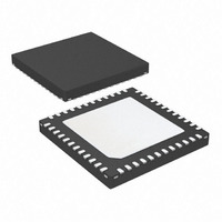
ATA5279P-PLQW Atmel, ATA5279P-PLQW Datasheet - Page 19

ATA5279P-PLQW
Manufacturer Part Number
ATA5279P-PLQW
Description
IC ANTENNA DVR SIX-FOLD 48QFN
Manufacturer
Atmel
Datasheet
1.ATA5279P-PLQW.pdf
(40 pages)
Specifications of ATA5279P-PLQW
Rf Type
PEG, TPMS
Frequency
125kHz
Features
RSSI Equipped
Package / Case
48-VQFN Exposed Pad, 48-HVQFN, 48-SQFN, 48-DHVQFN
Lead Free Status / RoHS Status
Lead free / RoHS Compliant
Available stocks
Company
Part Number
Manufacturer
Quantity
Price
Company:
Part Number:
ATA5279P-PLQW
Manufacturer:
ATMEL
Quantity:
3 500
Part Number:
ATA5279P-PLQW
Manufacturer:
ATMEL/爱特梅尔
Quantity:
20 000
9125L–RKE–03/11
LF data is transmitted on-off-keyed (OOK). “1” enables the field, whereas “0” disables it. Note
that the field generation strongly depends on the bandwidth (the Q factor) of the coil. If it is too
narrow, the receiver might not be able to decode the data correctly.
nal path from the modulator stage to the receiver.
Figure 3-12. Example for OOK-data Modulation with Atmel ATA5279
Coils with high Q values need more periods to reach the desired field strength and hence
appropriate detection level thresholds in the receiver. So the Q factor must be adapted in
order to ensure proper data communication. For example, the thresholds here are chosen at
70% of the required output current for a 0 to 1 and at 30% for a 1 to 0 detection.
The IC supports two data rates: standard, which is 3.9kbit/s (or 32LF periods), and high
speed, rated with 5.7kbit/s (or 22LF periods). Note that this refers to the encoded (net) data
rate. The minimum length of an active field (e.g., the time for the first 1 in
periods in standard and 11LF periods in high speed mode (i.e., gross data rate).
Another aspect of the LF data transmission is that current regulation can only be done roughly,
as the measurement must be interrupted over and over again. At a 0 to 1 transition, the cur-
rent measurement will not start until the 5th period, and there will not be any measurement
during a 0-transmission. The regulation precision that is achieved during carrier transmission
is not valid here.
As described in
avoid gaps in longer LF telegrams. The following example illustrates this feature.
Assume that following data words have been written into the command buffer via the SPI:
1. Send 2LF bits (SPI data 00h 05h)
2. Send carrier with a length of 24 data bits (SPI data 98h)
Transmitter Coil Current
Modulator Data
Receiver Data
Section 3.8 “Command Buffer” on page
off
off
1
1
0
0
Envelope
1
1
Current
16, data is processed seamlessly to
Receiver
1
1
Atmel ATA5279
Figure 3-12
Detection
0
Figure
Thresholds
1
1
shows the sig-
3-12), is 16LF
19


