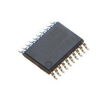
MCP4461T-104E/ST Microchip Technology, MCP4461T-104E/ST Datasheet - Page 75

MCP4461T-104E/ST
Manufacturer Part Number
MCP4461T-104E/ST
Description
IC DGTL POT 257TAPS 100K 20TSSOP
Manufacturer
Microchip Technology
Datasheet
1.MCP4441-103EML.pdf
(100 pages)
Specifications of MCP4461T-104E/ST
Package / Case
20-TSSOP (0.173", 4.40mm Width)
Temperature Coefficient
150 ppm/°C Typical
Taps
257
Resistance (ohms)
100K
Number Of Circuits
4
Memory Type
Non-Volatile
Interface
I²C, 2-Wire Serial
Voltage - Supply
2.7 V ~ 5.5 V
Operating Temperature
-40°C ~ 125°C
Mounting Type
Surface Mount
Number Of Pots
Quad
Taps Per Pot
257
Resistance
100 KOhms
Wiper Memory
Non Volatile
Buffered Wiper
Buffered
Digital Interface
I2C
Operating Supply Voltage
2.7 V to 5.5 V
Supply Current
600 uA
Maximum Operating Temperature
+ 125 C
Minimum Operating Temperature
- 40 C
Description/function
Quad I2C Digital POT with Nonvolatile Memory
Mounting Style
SMD/SMT
Supply Voltage (max)
5.5 V
Supply Voltage (min)
2.7 V
Lead Free Status / RoHS Status
Lead free / RoHS Compliant
Available stocks
Company
Part Number
Manufacturer
Quantity
Price
Part Number:
MCP4461T-104E/ST
Manufacturer:
MICROCHIP/微芯
Quantity:
20 000
8.4
The use of the General Call Address Increment,
Decrement, or Write commands is analogous to the
“Load” feature (LDAC pin) on some DACs (such as the
MCP4921). This allows all the devices to “Update” the
output level “at the same time”.
For some applications, the ability to update the wiper
values “at the same time” may be a requirement, since
they delay from writing to one wiper value and then the
next may cause application issues. A possible example
would be a “tuned” circuit that uses several MCP44XX
in rheostat configuration. As the system condition
changes (temperature, load, etc.) these devices need
to be changed (incremented/decremented) to adjust for
the system change. These changes will either be in the
same direction or in opposite directions. With the
Potentiometer device, the customer can either select
the PxB terminals (same direction) or the PxA
terminal(s) (opposite direction).
Figure 8-6
6*T
1*T
FIGURE 8-6:
Updates.
© 2010 Microchip Technology Inc.
Note:
I2CDLY
I2CDLY
T
I2CDLY
Normal Operation
General Call Operation
Using the General Call Command
time in “General Call” operation.
shows that the update of six devices takes
time in “normal” operation, but only
The application system may need to
partition the I
ensure that the MCP44XX General Call
commands do not conflict with the General
Call commands that the other I
may have defined. Also if only a portion of
the MCP44XX devices are to require this
synchronous operation, then the devices
that should not receive these commands
should be on the second I
= Time from one I
T
T
I2CDLY
I2CDLY
INC
POTs 01-06
Example Comparison of “Normal Operation” vs. “General Call Operation” Wiper
INC
POT01
2
C bus into multiple busses to
T
T
I2CDLY
I2CDLY
2
C command completed to completing the next I
INC
POTs 01-06
2
INC
POT02
C bus.
2
C devices
T
T
I2CDLY
I2CDLY
INC
POTs 01-06
INC
POT03
T
T
I2CDLY
I2CDLY
Figure 8-5
cases, the single I
adequate. For applications that do not want all the
MCP44XX devices to do General Call support or have
a conflict with General Call commands, the multiple I
bus configuration would be used.
FIGURE 8-5:
Configurations.
INC
POTs 01-06
Multiple I
Single I
Controller
Controller
INC
POT04
Host
Host
Bus b
Bus n
T
T
2
I2CDLY
I2CDLY
shows two I
C Bus Configuration
2
C Bus Configuration
Bus a
MCP444X/446X
Device 1b
Device 1n
2
Device 1a
INC
POTs 01-06
Device 1
C command.
INC
POT05
Device 2b
Device 2n
Device 2a
Device 2
2
Typical Application I
C bus configuration will be
2
T
T
C bus configurations. In many
I2CDLY
I2CDLY
Device 3n
Device 3b
Device 3a
Device 3
INC
POTs 01-06
Device 4n
Device 4a
Device 4b
Device 4
INC
POT06
DS22265A-page 75
Device nb
Device nn
Device na
Device n
2
C Bus
2
C


