Chameleon-AVR Nurve Networks, Chameleon-AVR Datasheet
Chameleon-AVR
Specifications of Chameleon-AVR


Related parts for Chameleon-AVR


Chameleon-AVR Summary of contents
Page 1
...
Page 2
... CHAMELEON™ AVR 8-Bit User Manual v1.0 “Exploring the CHAMELEON AVR 8-Bit – A Guide to Programming the CHAMELEON AVR 8-Bit System” Copyright © 2009 Nurve Networks LLC Author Andre’ LaMothe Editor/Technical Reviewer The “Collective” Printing 0001 ISBN Pending All rights reserved. No part of this user manual shall be reproduced, stored in a retrieval system, or transmitted by any means, electronic, mechanical, photocopying, recording, or otherwise, without written permission from the publisher ...
Page 3
... Licensing, Terms & Conditions NURVE NETWORKS LLC, . END-USER LICENSE AGREEMENT FOR CHAMELEON AVR HARDWARE, SOFTWARE , EBOOKS, AND USER MANUALS YOU SHOULD CAREFULLY READ THE FOLLOWING TERMS AND CONDITIONS BEFORE USING THIS PRODUCT. IT CONTAINS SOFTWARE, THE USE OF WHICH IS LICENSED BY NURVE NETWORKS LLC, INC., TO ITS CUSTOMERS FOR THEIR USE ONLY AS SET FORTH BELOW. IF YOU DO NOT AGREE TO THE TERMS AND CONDITIONS OF THIS AGREEMENT, DO NOT USE THE SOFTWARE OR HARDWARE ...
Page 4
... The information herein will usually apply to newer versions but may not apply to older versions. Please contact Nurve Networks LLC for any questions you may have. Visit www.xgamestation.com & www.chameleon-dev.com for downloads, support and access to the Chameleon user community and more! For technical support, sales, general questions, share feedback, please contact Nurve Networks LLC at: support@nurve.net / nurve_help@yahoo.com © ...
Page 5
... CHAMELEON AVR 8-Bit” User Manual and Programming Guide LICENSING, TERMS & CONDITIONS .................................................................................................3 VERSION & SUPPORT/WEB SITE......................................................................................................4 “EXPLORING THE CHAMELEON AVR 8-BIT” USER MANUAL AND PROGRAMMING GUIDE .....5 0.0 INTRODUCTION AND ORIGINS..................................................................................................11 1.0 ARCHITECTURAL OVERVIEW ...................................................................................................13 1.1 Package Contents .....................................................................................................................................................................15 1.2 Chameleon AVR “Quick Start” Demo.....................................................................................................................................16 First Things First ...
Page 6
... INSTALLING THE TOOL CHAINS: AVRSTUDIO, ARDUINO, AND PROPELLER IDE ...........75 15.1 ATMEL’S AVR STUDIO TOOLCHAIN OVERVIEW...................................................................76 15.1.1 Installing AVR Studio 4.xx (Optional) ................................................................................................................................77 15.1.2 Installing the AVR ISP MKII Hardware (Optional) ..........................................................................................................81 TM 15.1.3 Installing WinAVR ..........................................................................................................................................................82 © 2009 NURVE NETWORKS LLC “Exploring the Chameleon AVR 8-Bit” 6 ...
Page 7
... UART AND RS-232 LIBRARY MODULE PRIMER ..................................................................145 18.1 The Architecture of the UART API Library and Support Functionality............................................................................146 18.2 Header File Contents Overview ...........................................................................................................................................147 18.3 API Listing Reference ..........................................................................................................................................................148 18.4 API Functional Declarations ................................................................................................................................................148 © 2009 NURVE NETWORKS LLC “Exploring the Chameleon AVR 8-Bit” 7 ...
Page 8
... Header File Contents Overview ...........................................................................................................................................195 23.2 API Listing Reference ..........................................................................................................................................................195 23.3 API Functional Declarations ................................................................................................................................................195 24.0 KEYBOARD LIBRARY MODULE PRIMER .............................................................................197 24.1 Header File Contents Overview ...........................................................................................................................................197 24.2 API Listing Reference ..........................................................................................................................................................198 © 2009 NURVE NETWORKS LLC “Exploring the Chameleon AVR 8-Bit” 8 ...
Page 9
... Native Mode / Bootloader mode ...........................................................................................................................................248 33.1 Developing Your Own Propeller Drivers.............................................................................................................................249 33.1.1 Adding SPIN Driver Support for the Status LED .............................................................................................................250 31.1.2 Adding AVR Support at the Client/Master Side...............................................................................................................252 © 2009 NURVE NETWORKS LLC “Exploring the Chameleon AVR 8-Bit” 9 ...
Page 10
... APPENDIX H – OVERCLOCKING THE AVR AND PROPELLER...................................................263 H.1 Overclocking the Propeller Microcontroller.........................................................................................................................263 H.2 Overclocking the AVR328P Microcontroller........................................................................................................................263 APPENDIX I: ASCII / BINARY / HEX / OCTAL UNIVERSAL LOOKUP TABLES ..........................264 APPENDIX J: ANSI TERMINAL CODES.........................................................................................266 Examples ..................................................................................................................................................................................267 © 2009 NURVE NETWORKS LLC “Exploring the Chameleon AVR 8-Bit” 10 ...
Page 11
... I/O. The selection of the processors was difficult as it always is. We have to balance price, performance, user base, flexibility and a number of other factors. Additionally, since the Chameleon is a dual processor design, I had to think of a clean way to interface the processors such as shared memory, SPI, I use the Atmel AVR AT328P processor for the Master and the Parallax Propeller chip for the Slave ...
Page 12
... Arduino software and tools on the Chameleons. Of course, I was using the new Atmel 328P in my designs and Arduino was still using the Atmel 168, but I hoped they would upgrade in time and they did! So now the Chameleons will run the Arduino tool chain and you can use Chameleons as supped up Arduinos'. Of course, our boards are physically different and our headers are slightly different, but more or less with a little work any program designed for the Arduino can be ported to the Chameleon in a matter of minutes ...
Page 13
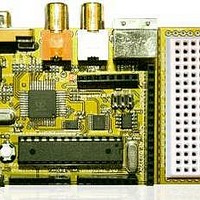
... Architectural Overview The Chameleon AVR 8-Bit or simply the “Chameleon AVR” is developed around the Atmel 8-Bit Mega AVR 328P28- Pin DIP QFP. Figure 1.1 shows an image of the Chameleon AVR 8-bit annotated. The Chameleon AVR has the following hardware features: 28-Pin DIP Package version of the AVR 328P, runs at 16 MHz with a maximum speed of 20 MHz suggested by Atmel ...
Page 14
... LCD screen and looks ugly. Also, there are some controls for the program that you must use some external push button switches to set, but it would be nice if you had a keyboard or mouse for user input. This is no problem for the chameleon! You would take you original program, compile it for the Chameleon, then add a few lines of code from our NTSC or VGA API that command the Propeller to draw text on the screen ...
Page 15
... Mini B USB cable to go from PC to Chameleon AVR. AVR MK II ISP Programmer. The Chameleon will run off the USB cable, so you do not require a wall adapter for development. Also, the Chameleon AVR is pre-loaded with the Arduino bootloader, therefore, if you use the Chameleon in “Arduino mode” only you will not need an Atmel AVR ISP MK II programmer, but we recommend one so that you can use AVR Studio to write more advanced C/C++ and ASM programs and to have more control over the platform ...
Page 16
... Step 3: Plug your 9V DC wall adapter in and plug the 2.1mm connector into the bottom right power port on the Chameleon AVR. If you do not have a power adapter then you can power the Chameleon AVR with the USB port. Plug a USB mini-B cable from you PC to your Chameleon AVR. We suggest using a powered USB hub since the Chameleon will draw a lot of power ...
Page 17
... The demo took about a week to develop and was written by one of our Demo coder’s JT Cook to see what he could do wit the Chameleon in a week and rely 100% on our drivers. The results are pretty amazing, and the cool thing is the game literally was ported to the PIC version in a matter of minutes extra bonus by leveraging the Propeller to do all ...
Page 18
... Figure 1.4 – The Atmel Mega AVR 328P packing for 28-Pin TQFP and PDIP packages. © 2009 NURVE NETWORKS LLC “Exploring the Chameleon AVR 8-Bit” 18 ...
Page 19
... The Atmel AVR 328P (P stands for Pico Power) comes in a number of packages including 28-pin DIP (duel inline package). We are using the Mega AVR 328P DIP package in the Chameleon. Figure 1.4 shows the packaging and pin out of the chip. The AVR 328P was designed as a general purpose, high performance microcontroller with an 8-bit data path, single clock execution on many instructions, as well as support for 16-bit operations and built in multiply instructions ...
Page 20
... FLASH since there is a limit to the number of times it can be re-written; 100,000 give or take. Additionally, you can use the 1MByte SPI FLASH on the Chameleon as well for storage. FLASH memories typically have a maximum number of times they can be written; ...
Page 21
... However, due to register space allocation there is a shift in the addresses; the first 256 byte addresses are used to access registers and system I/O then from address [$0100 - $08FF] is the 2K block of free memory. Not shown in the © 2009 NURVE NETWORKS LLC “Exploring the Chameleon AVR 8-Bit” Figure 1.6 – FLASH and SRAM memory layouts. ...
Page 22
... ASM files using Atmel ASM directives and syntax, they are assembled and linked and a final binary image is generated ready for download to the target (Chameleon in this case). This is not how we will use the tool in most cases. Typically, we will use it in GCC mode can code in both C and ASM. However, when you use the GCC mode of operation you are using the entire GCC tool chain including GCC (the C compiler), GAS (GNU assembler), make, librarian and so forth ...
Page 23
... ASM. The Atmel assembler is a little cleaner in my opinion, but GAS is fine as well. In any event, when you create a new project for the Chameleon you will select GCC and then you can write . (asm) files and then will be compiled, assembled and linked together. More of the mechanics of this later, but that’s the idea. ...
Page 24
... P30 - Serial Tx to host. P31 - Serial Rx from host. VDD --- 3.3 volt power (2.7 – 3.6 VDC) VSS --- Ground © 2009 NURVE NETWORKS LLC “Exploring the Chameleon AVR 8-Bit” Figure 1.9 – The Propeller pinouts. Table 1.4 – Propeller pin and signal descriptions. 24 ...
Page 25
... You simply write your code and run core. Then if that code crashes or is broken it does not affect the other cores at all! This is exactly what the Chameleon needs – a way to run multiple processes that each perform some kind of media task and then these processes wait for the master (the AVR) to send commands. Each core does not care what the neighboring cores are doing, only what it is doing. Luckily, if this all sounds like this is way too complicated, you don’ ...
Page 26
... In this section, we are going to cover every one of the Chameleon AVR’s hardware sub-sections, so you can get an idea of what’s going on and how the systems and signals are routed. Taken as a whole the Chameleon is rather complex, but as you will see, each individual sub-system is rather straightforward. Let’s begin with a birds eye view of the entire system schematic on the next page in landscape mode (Figure 2 ...
Page 27
... NURVE NETWORKS LLC “Exploring the Chameleon AVR 8-Bit” 27 ...
Page 28
... Figure 2.1(b) – The complete Chameleon AVR 8-bit PCB layout. © 2009 NURVE NETWORKS LLC “Exploring the Chameleon AVR 8-Bit” 28 ...
Page 29
... Figure 2.1 – The Chameleon AVR power supply design. The Chameleon AVR system has a duel 3.3V / 5.0V power supply system that is feed by a single 9V DC unregulated input from a wall adapter or feeds from the USB port header. The supplies design is shown in Figure 3.1 for reference. ...
Page 30
... The interface is typically 6-pin, but some hardware uses a 10-pin interface as well. The ISP interface was designed to be controlled by either a simple RS-232 or parallel interface with a modicum of hardware. The Chameleon AVR, uses the 6- pin interface variant as shown in Figure 4.2(a) (located right below the Propeller I/O port header). ...
Page 31
... Figure 5.1. © 2009 NURVE NETWORKS LLC “Exploring the Chameleon AVR 8-Bit” Table 4.1 – AVR ISP signals. I/O ...
Page 32
... Typically, you will leave the switch in down (AVR mode) most of the time unless you are TIP constantly re-programming the driver on the Propeller chip. © 2009 NURVE NETWORKS LLC “Exploring the Chameleon AVR 8-Bit” Figure 5.1 – Serial port routing/selector switch. 32 ...
Page 33
... COM ports from the operating system’s perspective, but other than that. This magical little chip let’s us talk serial to the Chameleon with a USB port. FTDI has written drivers for Windows, Linux, and Mac these chips are quite popular since its very difficult to find a real DB9 RS-232 serial port anymore. You can take a look at the data sheet for the chip here: DVD-ROM: \ CHAM_AVR \ DOCS \ DATASHEETS \ DS_FT232R ...
Page 34
... Moving on, the chip is very simple to interface, just power and an external XTAL (which is removable MHz. Take note of the SPI interface lines on the right, these are very important since they are used to communicate with the Propeller chip as well as the on board 1MB FLASH. © 2009 NURVE NETWORKS LLC “Exploring the Chameleon AVR 8-Bit” 34 ...
Page 35
... The Propeller can source up to 40mA per pin you tie 2 lines together and set them HIGH, you can source up to 80mA, more than enough for most applications. © 2009 NURVE NETWORKS LLC “Exploring the Chameleon AVR 8-Bit” Figure 8.1 – The Propeller Subsystem. ...
Page 36
... SPI selects to enable it. All the other SPI devices will be disabled and thus no bus contingency issues. 10.0 VGA Graphics Hardware In this chapter, we are going to take a look at the VGA hardware on the Chameleon AVR. The VGA hardware is very simple consisting of little more than (8) I/O lines, and (3) D/A converters based on resistors. The Propeller chip does all the work generating the VGA signal, but its nice to understand what’ ...
Page 37
... I checked on the Parallax Object Exchange. You can use any of these drivers with the Chameleon! You just need to modify the Propeller driver module, include the new VGA drivers, make connections to it via commands, and you are off and running. ...
Page 38
... Figure 10.1 – The Chameleon AVR VGA interface and support hardware. The VGA hardware for the Chameleon is very minimal since the Propeller chip is doing all the signal generation with direct control of the VGA signal via its built in VSU (video streaming unit). Of course, someone still has to write a driver for the VGA to work on the Propeller, but that’ ...
Page 39
... VGA mode (without any tricks). Not bad! For reference, the VGA connector has the following pin out shown in Table 10.3. The VGA port on the Chameleon AVR is a female HD15 (High Density) which is standard on the back of video card hardware. It will connect to any VGA monitor, but be careful when making connections, it’s a special “low profile” ...
Page 40
... Ground 7 -GREEN Ground 8 -BLUE Ground -GROUND 11 ID0 (Ground) 12 ID1 (NC) 13 VSYNC 14 HSYNC 15 NC © 2009 NURVE NETWORKS LLC “Exploring the Chameleon AVR 8-Bit” BLACK BLACK/WHITE BROWN BROWN/WHITE RED+SHIELD ORANGE YELLOW MINT GREEN NC GREEN BLUE PURPLE GREY WHITE SHRIMP 40 ...
Page 41
... Typically, designers like to run the system dot clock at this frequency and compute all events as a number of clocks, for example, getting ahead of myself, take a look at Figure 10.3(b), the Hsync pulse which is labeled “B” in the table (and a © 2009 NURVE NETWORKS LLC “Exploring the Chameleon AVR 8-Bit” Figure 10.3 – The VGA timing specifications. ...
Page 42
... You might be wondering where the 25.175 MHz clock is generated on the Chameleon? NOTE Well, the Propeller chip is generating the signal and it has internal counters and PLLs that generate the 25 ...
Page 43
... I/O pins manually with pure software as well. Either way, let’s take a look at the mechanics of the signal. On the Chameleon AVR for example, there are 2-bits per channel, so the encoding of the VGA data byte is as simple as generating bytes in the format shown in Figure 10.4. ...
Page 44
... Programming for the Propeller Powered HYDRA” which you can find on Amazon.com, Parallax.com, and XGameStation.com. There is also some minimal © 2009 NURVE NETWORKS LLC “Exploring the Chameleon AVR 8-Bit” Table 11.1 – The Video Hardware. ...
Page 45
... These two formats are incompatible with each other; one would need to be converted to the other before any common processing could be done. Interlaced scanning is where each picture, referred frame, is divided into two separate sub-pictures, referred to as fields. © 2009 NURVE NETWORKS LLC “Exploring the Chameleon AVR 8-Bit” 45 ...
Page 46
... A progressive, or non-interlaced, picture is painted on the screen by scanning all of the horizontal lines of the picture in one pass from the top to the bottom. This is illustrated in Figure 11.4. Figure 11.4 - Progressive (non-interlaced) scanning system. © 2009 NURVE NETWORKS LLC “Exploring the Chameleon AVR 8-Bit” Figure 11.3 - Interlaced scanning system. 46 ...
Page 47
... RCA jack. This is the same connector as that used for standard line level audio connections. S- video of course is slightly cleaner since the analog mixing of chroma and luma does NOT take place. A typical waveform of an all-white NTSC composite video signal is shown in Figure 11.5 (a). © 2009 NURVE NETWORKS LLC “Exploring the Chameleon AVR 8-Bit” PAL HDTV/SDTV ...
Page 48
... Figure 11.6 (b) depicts yet another timing drawing the NTSC video signal, this time, more formally labeled at the RS-170A color standard created in the early 1950’s as the successor to the B/W only RS-170 standard created 1941. © 2009 NURVE NETWORKS LLC “Exploring the Chameleon AVR 8-Bit” 48 ...
Page 49
... In general here are the steps to generating an NTSC signal. © 2009 NURVE NETWORKS LLC “Exploring the Chameleon AVR 8-Bit” 49 ...
Page 50
... Thus, most games systems don’t waste draw them, and simple increase the overscan regions good rule of thumb is that active video should be from 192-224 lines with equal amount of top and bottom overscan. © 2009 NURVE NETWORKS LLC “Exploring the Chameleon AVR 8-Bit” 50 ...
Page 51
... This is a 3.579594 MHz “tone” signal that the TV locks onto and uses as a phase reference for the remainder of the video line. The color of each pixel is determined by the © 2009 NURVE NETWORKS LLC “Exploring the Chameleon AVR 8-Bit” 51 ...
Page 52
... For each color clock on the active scan line, you must generate a 3.579594 MHz sine wave, this must ride on top or be superimposed on the luminance signal (the Chameleon AVR hardware does all this). The overall amplitude of the signal is the brightness or luminance just as it was with B/W, but the color signal’ ...
Page 53
... I/O pins and write our own driver. Or use one of the mouse/keyboard drivers already written for the Propeller which is the tactic we use for the Chameleon. More or less every single device interfaced uses a standard pre-written driver and all make calls to it from the AVR chip. But, its nice to know how these things work, so let’ ...
Page 54
... T 2C F0, F0, F0, F0, F0, F0, F0, F0,45 © 2009 NURVE NETWORKS LLC “Exploring the Chameleon AVR 8-Bit” . Description Keyboard clock signal, open collector. Keyboard data signal, open collector. Table 12.2 – Default scan codes. KEY MAKE BREAK 9 46 F0, F0, F0, FO, F0,5D BKSP ...
Page 55
... DIN’s pin out is shown in Figure 12.2 (referenced looking at the computer’s female side where you plug the keyboard into, notice the staggering of the pin numbering). Figure 12.2 - Female PS/2 6-Pin Mini Din Connector at Chameleon AVR socket. Table 12.3 lists the signals for reference, the descriptions of the signals are as follows: Bi-directional and used to send and receive data ...
Page 56
... Step 1: Wait for the keyboard to stop sending data (if you want to play nice). This means that both the DATA and CLOCK lines will HIGH state. © 2009 NURVE NETWORKS LLC “Exploring the Chameleon AVR 8-Bit” Figure 12.3 – Keyboard Serial Data Packet. ...
Page 57
... INT 16, `-------- A in period formula (see below `------------ B is period formula (see below) | `---------------- typematic delay `------------------ always zero © 2009 NURVE NETWORKS LLC “Exploring the Chameleon AVR 8-Bit” Table 12.4 – Keyboard Commands. (0=off, 1=on) (0=off, 1=on) (0=off, 1=on) ...
Page 58
... Again, we will cover real programming examples in the Programming Manual, but let’s just review the technical details briefly to get acquainted with the commands and data. © 2009 NURVE NETWORKS LLC “Exploring the Chameleon AVR 8-Bit” 58 ...
Page 59
... Mouse Data Packets The PS/2 mouse sends the movement information to the host which includes the position counters, button state, overflow flags and sign bits in the format show in Table 12.6. © 2009 NURVE NETWORKS LLC “Exploring the Chameleon AVR 8-Bit” Actual Movement Reported ...
Page 60
... Reporting Disabled". This means the mouse will not issue any movement data packets until it receives the "Enable Data Reporting" command. The various modes of operation for the mouse are: © 2009 NURVE NETWORKS LLC “Exploring the Chameleon AVR 8-Bit” Table 12.6 – Mouse data packet format. ...
Page 61
... After receiving the sample rate, the mouse again responds with "acknowledge" ($FA) and resets its movement counters. Most mice accept sample rates of 10, 20, 40, 60, 80, 100 and 200 samples/sec. © 2009 NURVE NETWORKS LLC “Exploring the Chameleon AVR 8-Bit” 61 ...
Page 62
... If the mouse is in Stream mode, the host should disable data reporting (command $F5) NOTE before sending any other commands. This way, the mouse won’t keep trying to send packets back while the host is trying to communicate with the mouse. © 2009 NURVE NETWORKS LLC “Exploring the Chameleon AVR 8-Bit” Bit 6 Bit 5 Bit 4 ...
Page 63
... The Propeller chip has its own 8-bit local I/O port located right under the composite video and PS/2 ports. The other headers surrounding the Chameleon PCB interface mostly to the AVR chip. Let’s take a look at the PCB for a moment for reference as shown in Figure 13.1. ...
Page 64
... Similarly, we used the name naming conventions for the signals such as Dn for digital I/Os and AINn for analog inputs. However, the Chameleon has a few extra signals mostly on the larger 16-pin header on the right. Signals such as the multiple power sources as well as the SPI multiplexer chip selects SPI_SS1n and SPI_SS0n respectively ...
Page 65
... The Propeller does have counters on board and can generate PWM signals, thus the audio drivers typically leverage these hardware elements. Thus, for most audio applications that connect to a Propeller chip all you need is a typical PWM “integrator” or “low pass” filter. The Chameleon employs such a hardware design as shown in Figure 14.1. ...
Page 66
... NURVE NETWORKS LLC “Exploring the Chameleon AVR 8-Bit” Gain ...
Page 67
... A .WAVE file for example is PCM data, you simply output the data at the proper rate to a D/A converter with an amplifier © 2009 NURVE NETWORKS LLC “Exploring the Chameleon AVR 8-Bit” 67 ...
Page 68
... use the Chameleon AVR’s internal timers we can do this (more on this later can write a software loop to do it. For example, if you wanted to hear a 500KHz, 1KHz, and 2KHz signal you just write a software loop that toggles the output AUDIO_MONO at that rate and you will hear the sound on the attached output device. Figure 14.3 shows this graphically. Now, there are a couple problems with this ...
Page 69
... Figure 14.4(b) there are 10 total cycles and them we have 50% duty cycles for a total analog voltage per 10 clocks of: Average Signal @ 20% duty cycle = (5V)* (50%)*[ (100 ns) / (1000 0.5V. © 2009 NURVE NETWORKS LLC “Exploring the Chameleon AVR 8-Bit” Figure 14.4 - Duty cycle modes. 69 ...
Page 70
... We will get more into the programming of PWM when we discuss sound generation in the programming section of the manual. But, for now realize that the low pass filter (LPF) that the Chameleon AVR uses on the audio circuit acts as a LPF as well as an “averaging” circuit for PWM has two uses – pretty cool. ...
Page 71
... First, let’s look at the maximum signal frequency, if you want to play back all 256 sine samples then the maximum “signal” frequency is always: © 2009 NURVE NETWORKS LLC “Exploring the Chameleon AVR 8-Bit” 71 ...
Page 72
... OR just using the upper 8-bits at the index into our 256 element sine table (the later is preferred). Then we simply need the magic number © 2009 NURVE NETWORKS LLC “Exploring the Chameleon AVR 8-Bit” Figure 14.7 – Our final PWM setup. ...
Page 73
... PHASE_INC = 65536 * 2550 / 256,000 = 652.8 Now, this is a decimal number which will be truncated during the fixed point math to 652, but this is fine, that’s only an error or: © 2009 NURVE NETWORKS LLC “Exploring the Chameleon AVR 8-Bit” PHASE_INC PHASE_ACC PHASE_ACC (upper 8-bits) ...
Page 74
... In conclusion, that’s a taste of what goes into generating sounds on the Propeller chip. Then there is the whole other process of creating a sound engine on top of these techniques to play “music” such as MIDI or MOD. © 2009 NURVE NETWORKS LLC “Exploring the Chameleon AVR 8-Bit” PHASE_INC ...
Page 75
... AVRStudio you can work with the Arduino toolchain alone. However, I still recommend you skim the discussion of AVRStudio since it’s a much more powerful tool than the Arduino tool. Additionally, the Chameleon has a Parallax Propeller chip on it have to install that tool as well, so there is a lot to do. We are going to show the installations of the tool in the following order: ...
Page 76
... Figure 15.1 – The relationship of the various AVR programming tools in the tool chain. Referring to Figure 15.1, you can see that there are three main components of the tool chain for the Chameleon AVR and AVR processors in general, they are: AVR Studio 4.xx ...
Page 77
... AVRISP MKII – This is the actual hardware programmer that is recommended for the Chameleon AVR 8-Bit. The programmer only supports programming and not debugging, but is low cost and very versatile. The programmer must be installed as well and its firmware potentially updated. This installation will be done after the other tools are installed, so AVR Studio 4 ...
Page 78
... Press <Next> this will take you to the licensing screen shown in Figure 15.3 below. The license screen is the usual you would expect, simply press <Next> to continue. This brings up the installation target directory as shown in Figure 15.4 below. © 2009 NURVE NETWORKS LLC “Exploring the Chameleon AVR 8-Bit” Figure 15.3 – AVR Studio License Agreement. 78 ...
Page 79
... In any event, select the USB driver upgrade to save you the time of installing it later. This option includes the needed driver for any external USB based programmer/debugger which we need. Press <Next> and the final installation confirmation dialog will display as shown in Figure 15.6. © 2009 NURVE NETWORKS LLC “Exploring the Chameleon AVR 8-Bit” 79 ...
Page 80
... Make sure to reboot your machine to allow the system to configure and all the TIP environment variables to get set correctly. The WinAVR step of the installation depends on the previous installation of AVR Studio want to make sure everything is clean. © 2009 NURVE NETWORKS LLC “Exploring the Chameleon AVR 8-Bit” 80 ...
Page 81
... Select the radio button to install the software automatically and then click <Next>. Unless something went wrong with the AVR Studio installation you should see the hardware being installed as shown in Figure 15.9 below. Figure 15.9 – Windows installation AVR ISP hardware and drivers. © 2009 NURVE NETWORKS LLC “Exploring the Chameleon AVR 8-Bit” 81 ...
Page 82
... Once you have located the installation file, go ahead and launch it, you will see the language splash screen as shown in Figure 15.11 below (ignore the version differences from our screen shots to the latest copy on the DVD). © 2009 NURVE NETWORKS LLC “Exploring the Chameleon AVR 8-Bit” party compiler which costs lots of $$$ ...
Page 83
... Click <Next> and the famous GNU GPL license agreement should display on your screen. Read it and then click <I Agree> to continue as shown in Figure 15.13 below. © 2009 NURVE NETWORKS LLC “Exploring the Chameleon AVR 8-Bit” Figure 15.11 – WinAVR language selection. ...
Page 84
... The WinAVR components selection dialog is straightforward and mostly redundant (of course I want to install the files!). In any event, simply check all checkboxes and then click <Install> to initiate the installation process. The installation progress dialog should display as shown in Figure 15.16 below. © 2009 NURVE NETWORKS LLC “Exploring the Chameleon AVR 8-Bit” 84 ...
Page 85
... The installation is rather quick (under a minute). When complete, the installation finished message box will display, click <Finish> to complete the process and you can stop holding your breath ☺ © 2009 NURVE NETWORKS LLC “Exploring the Chameleon AVR 8-Bit” Figure 15.17 – WinAVR successfully installed! ...
Page 86
... Alright, we are going to approach all development with the Chameleon AVR is as simple as possible. To that end, we need to create a single project to work with then for each demo we will simply include the source files in the source tree that the demo needs and remove ones it doesn’ ...
Page 87
... Simulator 2” along with “ATmega328P” under Device. The software simulator is of some use, but you will find its capabilities limited. Moreover, it only simulates the processor not any the hardware connected to it. Thus, in the future, you might want to purchase the AVR JTAG ICE debugger or other similar 3 © 2009 NURVE NETWORKS LLC “Exploring the Chameleon AVR 8-Bit” rd party tool. ...
Page 88
... Files” folder as shown in Figure 15.22 below. Figure 15.22 – The AVR Studio GCC Source Files folder. © 2009 NURVE NETWORKS LLC “Exploring the Chameleon AVR 8-Bit” 88 ...
Page 89
... Once you launch the tool then you should see the very complex interface shown in Figure 15.24 below. Figure 15.24 – The Project Options tool which sets up the entire tool chain. © 2009 NURVE NETWORKS LLC “Exploring the Chameleon AVR 8-Bit” 89 ...
Page 90
... The WinAVR uses intermediate format before the final binary AVR hex image is generated that we will download into the Chameleon each time. Under the “Output File Directory:”, you can set anything you wish, but for now set it to “\default” as shown in the figure. ...
Page 91
... Below is a small sample of a .LSS file, specially the code generated by one of the graphics functions in the API VGA_Color(…): © 2009 NURVE NETWORKS LLC “Exploring the Chameleon AVR 8-Bit” 91 ...
Page 92
... FLASH. Encoded in the format are addresses, starting locations, and data, so the entire FLASH need not be programmed if the final .HEX file is only a few hundred bytes long: © 2009 NURVE NETWORKS LLC “Exploring the Chameleon AVR 8-Bit” 92 ...
Page 93
... Next, up click the “Custom Options” tab to the left, this should bring up the dialog shown in Figure 15.26. Figure 15.26 – The “Custom Options” tab of the Project Options dialog. © 2009 NURVE NETWORKS LLC “Exploring the Chameleon AVR 8-Bit” 93 ...
Page 94
... If you navigate into the “\Source” directory, this is where the project we created should reside in a directory called “\cham_avr_work_01”. Yours should looks something like the listing shown in Figure 15.28 if you navigate into the project directory. © 2009 NURVE NETWORKS LLC “Exploring the Chameleon AVR 8-Bit” 94 ...
Page 95
... Like all IDEs there are a couple ways to do this, but the most straightforward is to highlight the “Source Files” folder under the project tree and right click the mouse to get a context menu. This is shown in Figure 15.29 below. Figure 15.29 – Adding source files to the project. © 2009 NURVE NETWORKS LLC “Exploring the Chameleon AVR 8-Bit” 95 ...
Page 96
... Rebuild All > from the Main Menu. This will start the building process which consists of compilation, linking, and finally hex file generation for the AVR target. © 2009 NURVE NETWORKS LLC “Exploring the Chameleon AVR 8-Bit” - This is the main “system” file that is needed for all applications. ...
Page 97
... If the build was successful then you should see the compiler output in the bottom window as shown in Figure 15.32. © 2009 NURVE NETWORKS LLC “Exploring the Chameleon AVR 8-Bit” Figure 15.31 – Building our project at long last. 97 ...
Page 98
... This is the final result of all our hard work, now we just need to get it into the Chameleon AVR, so let’s see how to do that now. © 2009 NURVE NETWORKS LLC “Exploring the Chameleon AVR 8-Bit” ...
Page 99
... Make sure you have the AVR ISP USB cable connected to the PC and the 2x5 header cable from the AVR ISP programmer is plugged into the Chameleon AVR itself as shown in Figure 15.35. ...
Page 100
... Figure 15.35 – Plugging the AVR ISP MKII into the Chameleon AVR properly. When you are ready to go, the Chameleon AVR is connected to the AVR ISP and powered up. Go ahead and plug in the 9V DC power supply or make sure the USB cable is plugged into your PC then turn the unit on by sliding the power switch to the left. Now, hold your breath and click < ...
Page 101
... Signature> button and the tool will read the device signature out of the Chameleon AVR and check it against the device you have selected in the above list box. For example, the AVR Mega329P should have the signature: “0x1E 0x95 0x0F” ...
Page 102
... Referring to Figure 15.38, you can see there are a lot of fuse settings and a lot of cryptic labels on the left hand side. First, simply mimic what you see in the figure and set your fuses to exactly these values. Be specially cognizant of the settings for: © 2009 NURVE NETWORKS LLC “Exploring the Chameleon AVR 8-Bit” 102 ...
Page 103
... We are almost there, the very last tab of interest is the “Lockbits” tab, select this tab as shown in Figure 15.39. Figure 15.39 – The AVR ISP MKII control panel’s “Lockbits” tab. © 2009 NURVE NETWORKS LLC “Exploring the Chameleon AVR 8-Bit” 103 ...
Page 104
... However, the word “fuses” is used a convention for historical reasons more or less to this day. At this point, the programming tool is all set up for the Chameleon AVR and our development needs. Finally, it’s time to actually download the .HEX file we previously generated and is waiting in the “\cham_avr_work_01\default” folder on your hard drive. Re-select the “ ...
Page 105
... AVR chip. But, with the Arduino bootlooader, the Arduino tool talks to the AVR chip over a serial port (via the USB serial port on the Chameleon) and you can compiler and download programs. Figure 15.41 shows the relationship between the components of an Arduino like setup. ...
Page 106
... So, you edit your Sketch (program) in the Arduino editor, you compile it (with GCC under the hood) then finally you need to download it to the Chameleon. The Arduino tool calls another program AVRDude which does this and sends the binary image via the serial line with a special protocol agreed to between the bootloader and AVRDude. And that’s how it all ...
Page 107
... These two directories are needed to augment the Arduino default installation can compile Chameleon programs with the Arduino tool. The \LIBRARIES directory has all the Chameleon libraries ported over to work with the Arduino tool (very simple changes in most case) and the \SKETCHES directory has all the programs and demos from this manual in Arduino format for you ...
Page 108
... As you can see, there are a lot of files, hundreds if not a couple thousands with all the GNU stuff and Cygwin files buried in there. But, we luckily don’t have to worry about much of it, we just want to update the \LIBRARIES directory with the Chameleon packages can build Chameleon compatible programs this go ahead and dive down into the \HARDWARE directory this is shown in Figure 15.45. ...
Page 109
... These are all the libraries provided by the Arduino development system. Go ahead and take a look in a few to see what’s in them, then come back to the root directory as shown above. Now, what we need copy our new Chameleon libraries into this directory back to the DVD in the Arduino folder and copy the contents of the \LIBRARIES sub- folder into your install folder. When you’ ...
Page 110
... Figure 15.47 – The Arduino Libraries folder after copying the Chameleon libraries into it. As you can see, there are about a dozen new libraries that we have developed for the Chameleon to run in the Arduino environment. They are all uppercase to help you differentiate them. ...
Page 111
... DVD-ROM:\ CHAM_AVR \ TOOLS \ DRIVERS \ USBDriverInstallerV2.04.16.exe After you have installed the driver, then each time you plug a Chameleon AVR into the PC via the USB port, the FTDI chip will assign a NEW COM port, you need to determine what COM port it attached itself to? Goto Windows Start menu on and select < ...
Page 112
... Chameleon AVR 8-bit ←-----Mini USB cable----------→PC Running Terminal Program (eg. PuTTY) The PC can talk to either the Propeller chip onboard the Chameleon via the USB port OR the standard serial port on the AVR chip, this is accomplished via a mechanical switch at the bottom of the board shown in Figure 15.49 below. ...
Page 113
... Figure 15.51. Data Format: "N81", no parity, 8 data bits, 1 stop bit. Baud Rate: 115200. Handshaking: None. Figure 15.51 - PuTTY Setup for serial communications with Chameleon AVR, 115200 baud, N81, continued. © 2009 NURVE NETWORKS LLC “Exploring the Chameleon AVR 8-Bit” 113 ...
Page 114
... To launch the terminal program, you would press <Open> which opens a new terminal window. This is where you would type on the PC keyboard to communicate with the Chameleon AVR and run the demos or do serial terminal experiments. 15.2.3.1 Running the Arduino Tool We are all ready to go, let’ final checklist before we launch the tool: 1 ...
Page 115
... New Sketch – Creates a new sketch. Open Sketch – Opens a sketch. Save Sketch – Saves the current sketch. Upload Sketch – Compiles and uploads the sketch to the Chameleon (Arduino). Serial Monitor – Launches a serial monitor terminal program. Tab Controls – Standard tab controls to add more views. ...
Page 116
... Next, we need to make sure that the Arduino tool has the correct serial port and the correct target chip this, select the <Tools→Board> from the main menu and select “Arduino Duemilanove or Nano w/ ATMega 328” which is the top most item. This is shown in Figure 15.55. © 2009 NURVE NETWORKS LLC “Exploring the Chameleon AVR 8-Bit” 116 ...
Page 117
... Next, we need to make sure that the Arduino tool is using the proper serial port. You should have noted this earlier when you plugged the USB cable into the Chameleon and the PC recognized the FTDI USB to serial chip. If you haven’t done then, plug the USB cable in, and go thru the installation of the FTDI drivers. Then take not in the Control Panel where the new USB serial port was installed, you need that information for this step ...
Page 118
... However, you can copy a sketch from the sketches directory to another system or the entire sketches directory usually without a problem. In any event, let’s load a “Hello World” sketch into the Arduino tool, compile and download to the Chameleon. Here are the steps to get things ready: Step 1: Make sure the Chameleon is powered, the USB cable is plugged into it ...
Page 119
... Figure 15.57 – Loading our first “Hello World” sketch. Once you load the sketch the tool should load the source for the “main” program as shown in Figure 15.58 below. © 2009 NURVE NETWORKS LLC “Exploring the Chameleon AVR 8-Bit” 119 ...
Page 120
... Binary sketch size: 1034 bytes (of a 30720 byte maximum) That’ you have compiled your very first Chameleon program using the Arduino tool! Hopefully, you can see the incredible power of the Chameleon. It leverages the toolchain and main processor of the Arduino, but adds a very powerful multicore processor (the Propeller the heavy lifting ...
Page 121
... Chameleon AVR (and PIC) uses a Propeller chip as the media processor, thus to program the Propeller chip’s EEPROM on the Chameleon with code we need to use this tool. The Propeller is a 32-bit processor and you program BASIC like language called SPIN, or you can program in Assembly language. The Propeller IDE supports both seamlessly. The assembly language is very nice, but SPIN takes a bit to get used as does the editor which uses indentation like Python for block level ...
Page 122
... Step 2: The installation type should be displayed next as shown below in Figure 15.60, select “Complete” install, click <NEXT>. Step 3: VERY IMPORTANT! The Propeller tool IDE communicates to the Chameleon AVR using a USB cable and driver, this USB driver must be installed. The next dialog shown below in Figure 15.61 should have the “Automatically Install/Update driver” ...
Page 123
... Step 6: Click <OK> and the final installation should take place, you will see a dialog like that shown in Figure 24.0 below, click <FINISH> and this should complete the installation of the Propeller Tool IDE and the associated USB drivers it needs. © 2009 NURVE NETWORKS LLC “Exploring the Chameleon AVR 8-Bit” 123 ...
Page 124
... The Propeller tool communicates to the Propeller chip over a single 2-line serial connection with the standard RS-232 TX/RX pair along with DTR (data terminal ready reset line. The Chameleon’s USB serial port is used for the communications channel for the Propeller chip. However, if you recall, the USB serial port can be used by the AVR or the Propeller ...
Page 125
... Once the source code is loaded into the tool, you simple have to download it into the Chameleon AVR. Make sure that you have the USB cable plugged into the Chameleon, power is ON, and the serial selection switch is in the UP position. When you are ready then you can press <F11> on the Propeller Tool, or from the main menu, you can select <RUN- > ...
Page 126
... Once the firmware is downloaded into the Propeller chip on the Chameleon board it will immediately start generating NTSC and VGA video. If you hit RESET on the Chameleon, you will see the images shown in Figure 15.68 on the NTSC and VGA monitors respectively. Figure 15.68 – The NTSC and VGA monitors showing the Chameleon AVR’s output after installing the Propeller © ...
Page 127
... Propeller chip is functioning correctly as well as to verify the LED is good. Finally, you will HEAR the Chameleon make sounds as it boots up, a series of tones that play musical notes when you hit RESET. Make sure to have the audio port plugged into your NTSC TV as well. These will all be part of the final tests for each Chameleon. Figure 15.69 – ...
Page 128
... Chameleon Inter-Processor Architecture Overview In this section, we are going to go into a bit of detail in relation to the software engineering techniques that the Chameleon’s duel processor architecture is based on. This section isn’t necessary to use the Chameleon, but its necessary to understand the design more completely. ...
Page 129
... Below is the list of current commands supported by the MCP by the default driver cham_default2_drv_112.spin: © 2009 NURVE NETWORKS LLC “Exploring the Chameleon AVR 8-Bit” Propeller IO Port Pins Used 12, 13, 14 (video LSB to MSB) ...
Page 130
... Once a valid command is detected then its parsed and a case handler in the MCP tries to dispatch it to the proper driver object (themselves running on other cores potentially). An excerpt from that section of the driver code looks like this: © 2009 NURVE NETWORKS LLC “Exploring the Chameleon AVR 8-Bit” 130 ...
Page 131
... In the sections below we will cover the exact drivers used, but the point is, they were chosen more or less for ease of use and user base. © 2009 NURVE NETWORKS LLC “Exploring the Chameleon AVR 8-Bit” 131 ...
Page 132
... Command Processing Loop – As SPI commands are sent over the SPI channel, the virtual SPI driver listens and if it detects traffic, it then processes the bytes and places them into a globally shared memory buffer. The MCP is sitting a © 2009 NURVE NETWORKS LLC “Exploring the Chameleon AVR 8-Bit” 132 ...
Page 133
... Also, there is a return value another 4-byte float, thus we need to “pack” the parameters up into a single record and pass it along and then wait for a single float (4-byte result). © 2009 NURVE NETWORKS LLC “Exploring the Chameleon AVR 8-Bit” 133 ...
Page 134
... But, let’s keep exploring the general idea of RPCs and some strategies that might help you later as you update/modify the default drivers shipped with the Chameleon. 16.3.1 ASCII or Binary Encoded RPCs When designing an RPC system you can make it really complex or really simple. The main idea is that you want to be able to call functions in another process, processor, machine. Decisions have to be made about the “ ...
Page 135
... RPC to perform calculations on. The database never changes need to keep sending it over and over, once its in the servers memory space, you can save the bandwidth. 16.3.3 Our Simplified RPC Strategy Considering all these interesting methods, the method used for the Chameleon is a 3-byte binary encoded SPI packets with the following format: [command8, data_low8, data_high8] Where command8 is an 8-bit command code, data_low8 and data_high8 are the operands for the command. Thus, each SPI packet is rather small and can’ ...
Page 136
... NTSC, VGA, audio and keyboard/mouse all running at the same time and be able to access these devices. In the future, you might want to use other objects or improve these for more specific needs. In any event, referring to Figure 16.5. The objects used are shown in Table 16.2. © 2009 NURVE NETWORKS LLC “Exploring the Chameleon AVR 8-Bit” 136 ...
Page 137
... NTSC terminal that might work better on some LCDs. You can drop down you have trouble with the default2 driver. Note 3: The Chameleon only has one PS/2 port, so only one driver; keyboard or mouse can be active at once. However, the default MCP driver can “hot” swap the drivers, so you can unplug the keyboard/mouse in real-time and with software “ ...
Page 138
... In the section below we will briefly cover each one of these libraries and the functions within them. Before, we get started let’s take a look at the “big picture” illustrating all the components of the Chameleon AVR development suite of software and tools. Figure 17.1 shows a system level architecture diagram of all the pieces involved. ...
Page 139
... C library functions you are used to. Therefore, when you create a C/C++ program for the Chameleon AVR and include say <stdio.h> you are including functions from the AVR Libc installation. Let’s talk about this for a moment. First, embedded systems are very unique in that they are very constrained, have little memory and resources ...
Page 140
... On the Chameleon AVR, this won’t work since the developer of AVR Libc has no idea about the Chameleon AVR, thus anything that is hardware specific won’t work since Libc has no idea about the hardware. On the other hand, you might ask “is it possible to get printf(…) to work?”. The answer is yes. However, you would have to go into the source files where printf(… ...
Page 141
... As you can see the first set of headers looks pretty familiar, but the second and third set are totally AVR specific, but not hardware specific to the Chameleon AVR, only to the AVR 328p processor. Now, the hardware specific functionality for the Chameleon AVR, we had to develop. Referring to Figure 17.1, there are a number of library classes you can glean from the figure, they are: System The system library module is a “ ...
Page 142
... With that in mind, there are a number of .C and .H files that make each up class of library functionality for the Chameleon API. At this point, we are going to drill down and list each of the files with a short description. Then we are going to discuss the key data structures and header files for each library module, list the functions one by one with examples ...
Page 143
... Lastly, so that the user can change the system frequency if he wishes during run-time, there is a variable shadow of the F_CPU constant that is loaded with said constant during startup. Thus, the variable is used in the Chameleon API library for calculations. This gives it typing information and as noted the ability to be changed during run-time, here’s the declaration: That wraps it up for the header file declarations ...
Page 144
... The function returns the value as a long thus all inputs have to fit into a signed long result. Returns 0 if the function can’t perform a conversion. Conversion examples from all bases. Example(s): © 2009 NURVE NETWORKS LLC “Exploring the Chameleon AVR 8-Bit” Resets the AVR chip. Resets the Propeller chip remotely. 144 ...
Page 145
... The “UART and RS-232” communications module supports basic transmission and reception of bytes to and from the Chameleon AVR serial port. The AVR 328P (“P” – Pico power version that we are using) has a single very advanced USART (Universal Synchronous and Asynchronous Serial Receiver and Transmitters connected directly to the TX/RX pins of the USB FTDI chip which allows serial communication via the USB port ...
Page 146
... CHAM__AVR_UART_DRV_V010.h The Arduino library has some built in C++ classes for serial I/O, thus when using the ARDUINO Chameleon with the Arduino tools, you do not need to use the UART library, you can TIP use the built in library the Arduino libraries provide. 18.1 The Architecture of the UART API Library and Support Functionality ...
Page 147
... If you are going to be using a lot of serial communications and know you are going to send large strings or receive large strings and not be able to interrogate the © 2009 NURVE NETWORKS LLC “Exploring the Chameleon AVR 8-Bit” 147 ...
Page 148
... Function Prototype: int UART_Init(unsigned int baudrate); Description: UART_Init(…) initializes USART0 (the primary USART connected to the SER1 serial port). The © 2009 NURVE NETWORKS LLC “Exploring the Chameleon AVR 8-Bit” Description Initializes UART, ISRs, etc. Shuts down the UART. Transmits a character using interrupt buffer. ...
Page 149
... Use this function is you don’t care about using the transmitter interrupt and can wait for the characters to transmit before the function returns. Function returns nothing. © 2009 NURVE NETWORKS LLC “Exploring the Chameleon AVR 8-Bit” 149 ...
Page 150
... UART_Newline() simply send a CR/LF (0x0A, 0x0D) to the UART. Assuming, a terminal program is Description: connected to the Chameleon AVR, this function is a nice helper to print newlines when needed. Returns nothing. Example(s): Assuming the Chameleon AVR is connected other terminal with VT100 capabilities, print 10 newlines. _________________________________________________________________________________________________ Function Prototype: void UART_Print_String(char *string); ...
Page 151
... Note that if you set wait = 1 the function could theoretically wait forever. Wait for the character ‘X’ when received blow up the world ☺ Example(s): © 2009 NURVE NETWORKS LLC “Exploring the Chameleon AVR 8-Bit” 151 ...
Page 152
... And to avoid licensing the I Atmel created generalized hardware that supports the I specifically for it. In any event, TWI = I © 2009 NURVE NETWORKS LLC “Exploring the Chameleon AVR 8-Bit” - Main C file source for “SPI and I - Header file for “SPI and I ...
Page 153
... Note: You might find some devices with slightly different naming conventions, but the idea is there is data out and data in, a clock, and some kind of chip select. If you refer back to the Chameleon’s SPI interface discussion in Section 9.0 of the Hardware Primer you can see that these signal pins are mapped from the AVR to the Propeller chip. ...
Page 154
... Note: Most SPI slaves default to mode 0, so typically this mode is what is used to initiate communications with a SPI device. Figure 19.2(a) – SPI timing diagrams for clock phase polarity (CPHA=0). © 2009 NURVE NETWORKS LLC “Exploring the Chameleon AVR 8-Bit” Table 19.2 – SPI clocking modes. CPOL (Clock Polarity) ...
Page 155
... SPI interface with I/O pins. For example, maybe you need (4) SPI interfaces all at the same time on the Chameleon’s expansion port, the only way to do this will manually with pin toggling. However, the AVR 328P’s USARTs (basically UARTs with extra features) both support “SPI modes”. In other words, even though the AVR 328P has a primary SPI controller, the USART on the AVR 328P can be put into “ ...
Page 156
... Everything begins with the “START” condition, that’s the first thing to remember with I show the timing waveforms for this event. © 2009 NURVE NETWORKS LLC “Exploring the Chameleon AVR 8-Bit” bus is laid out in relation to the master device, and the slaves Figure 19.3 – ...
Page 157
... Moreover, you may wish to develop much higher level functionality yourself. If you do, make note that the “SD card” library uses the SPI functions in this module, so you will have to emulate their functionality and linker names. © 2009 NURVE NETWORKS LLC “Exploring the Chameleon AVR 8-Bit” “ ...
Page 158
... Next, there are some timing constants that slow things down and make sure when SPI commands are sent to the Propeller the AVR waits long enough before issuing another command. These don’t matter too much as the drivers evolved, but were needed in earlier driver development: © 2009 NURVE NETWORKS LLC “Exploring the Chameleon AVR 8-Bit” and SPI interfaces): ...
Page 159
... NTSC modes. I wrote the tile engine to give you more performance and the ability to do some game like applications. These commands are more complex and it will take a bit to explain them, but for now, just peruse them below: © 2009 NURVE NETWORKS LLC “Exploring the Chameleon AVR 8-Bit” 159 ...
Page 160
... Mechatronics section for reference. So the functions work, but you have to call them at a fairly low level. Table 19.3 2 below lists the “SPI and I C” API functions categorized by functionality. © 2009 NURVE NETWORKS LLC “Exploring the Chameleon AVR 8-Bit” peripheral (a digital potentiometer) which we will cover in the 160 ...
Page 161
... Function Prototype: char TWI_Action(unsigned char command); The TWI_Action(…) function is very powerful since it really doesn’t do much other than pass the Description: © 2009 NURVE NETWORKS LLC “Exploring the Chameleon AVR 8-Bit” 2 C” module API functions listing. Description Initializes the TWI / I2C hardware. ...
Page 162
... API and fill them out. Currently, a much simpler approach is taken where the single “action” function (listed above) performs both any action as well as returns status and errors. Example(s): None. _______________________________________________________________________________________________ Function Prototype: int SPI_Init(unsigned char spi_rate); © 2009 NURVE NETWORKS LLC “Exploring the Chameleon AVR 8-Bit” 162 ...
Page 163
... It is important to remember that the SPI’s built in CS line is not used to select anything. Instead a pair of digital I/O lines are used as SPI “select” selection bits and are multiplexed to select devices named 0…3. The signals in the Chameleon design are on Port C #define SPI_CS0 #define SPI_CS1 To select device 0… ...
Page 164
... SPI device selected (enabled) at all times as long as you don’t have other SPI devices on the bus that can contend with the SD SPI interface. Example 2: Read 512 bytes from the SPI interface device 1 (assumes its been initialized somehow) and store in an array. © 2009 NURVE NETWORKS LLC “Exploring the Chameleon AVR 8-Bit” 164 ...
Page 165
... B when this set of conditions occur. That’s what the code above does processor A, the AVR, ask for too much, too fast, processor B, the Propeller, says “hold on a minute, let me finish the last thing!”. © 2009 NURVE NETWORKS LLC “Exploring the Chameleon AVR 8-Bit” rd ...
Page 166
... GFX_CMD_NTSC_CLS, and now send the command with a function call. _______________________________________________________________________________________________ Function Prototype: © 2009 NURVE NETWORKS LLC “Exploring the Chameleon AVR 8-Bit” rd byte of the command packet and retrieve the 3rd byte back in a buffer. 166 ...
Page 167
... NTSC Library Module Primer The basic premise of the Chameleon design is that it leverages drivers running on the Propeller chip to do all the media and graphics. Thus, whatever features the particular driver running on the Propeller side is the only features we can access via the AVR side. That doesn’t mean we can’t abstract functionality and add higher level functions that build on the sub-functions, however, this probably isn’ ...
Page 168
... Use them if you wish. However, once you have a really nice Propeller driver written you will definitely want to create more advanced API layers on the AVR side, so you can write high level code. But, in this case, most of the functions are 1:1 © 2009 NURVE NETWORKS LLC “Exploring the Chameleon AVR 8-Bit” 168 ...
Page 169
... Function Prototype: int NTSC_GetXY(int *x, int *y); NTSC_GetXY(…) returns the position (column, row) of the virtual cursor. Depending on the driver Description: © 2009 NURVE NETWORKS LLC “Exploring the Chameleon AVR 8-Bit” Description Clears the NTSC screen. Gets the current cursor position on the terminal. ...
Page 170
... X position (X follows). $0B = set Y position (Y follows). $0C = set color (color follows). $0D = return (carriage return and linefeed). Clear the screen then print “Chameleon”. Example(s): _________________________________________________________________________________________________ © 2009 NURVE NETWORKS LLC “Exploring the Chameleon AVR 8-Bit” 170 ...
Page 171
... VGA Library Module Primer The basic premise of the Chameleon design is that it leverages drivers running on the Propeller chip to do all the media and graphics. Thus, whatever features the particular driver running on the Propeller side is the only features we can access via the AVR side. That doesn’t mean we can’t abstract functionality and add higher level functions that build on the sub-functions, however, this probably isn’ ...
Page 172
... VGA_Term_Char(char ch); int VGA_Term_Print(char *string); int VGA_Color(int col); © 2009 NURVE NETWORKS LLC “Exploring the Chameleon AVR 8-Bit” - Main C file source for “VGA” module. - Header file for “VGA” module. Table 21.1 – “VGA” module API functions listing. ...
Page 173
... Description: position, updates the current cursor position, and potentially scroll the text screen up if printing on last line of display. Additionally, this function is a sub-command conduit to the “terminal manager”. This © 2009 NURVE NETWORKS LLC “Exploring the Chameleon AVR 8-Bit” 173 ...
Page 174
... Returns 1. Example(s): Print the character ‘X’ in all colors. _________________________________________________________________________________________________ © 2009 NURVE NETWORKS LLC “Exploring the Chameleon AVR 8-Bit” 174 ...
Page 175
... GFX Driver Architectural Overview The idea of the Chameleon is that you use other people’s drivers, make your own and change them as you need them on the Propeller side. Thus, we don’t want to spend too much time explaining how any particular driver works since you will © ...
Page 176
... Then we can make changes to the tile map using the high level “terminal” functions or the low level graphics functions (which is what this section is all about). © 2009 NURVE NETWORKS LLC “Exploring the Chameleon AVR 8-Bit” 176 ...
Page 177
... Atari 800 fonts as well as some extra characters for fun. The font file is located on the CD here: DVD-ROM:\ CHAM_AVR \ TOOLS \ GRAPHICS \ c64_font_05_16b.bmp Figure 22.2 shows a screen shot of the font file for reference. © 2009 NURVE NETWORKS LLC “Exploring the Chameleon AVR 8-Bit” 177 ...
Page 178
... Below is a peek at the palette definition in the driver: © 2009 NURVE NETWORKS LLC “Exploring the Chameleon AVR 8-Bit” nd byte is the color attribute which is an ...
Page 179
... By setting different bits you can create "colors" that represent these signals. For example, Table 22.1 below shows how to create black, sync, color burst, shades of gray, and colors with any intensity. Table 22.1 - Color encoding for various color values. © 2009 NURVE NETWORKS LLC “Exploring the Chameleon AVR 8-Bit” 179 ...
Page 180
... API, etc. are all handled at some point on the Propeller running the enhanced graphics driver for NTSC tile graphics. With that in mind, let’s crack open the C/C++ header file named: CHAM_AVR_GFX_DRV_V010.h and see © 2009 NURVE NETWORKS LLC “Exploring the Chameleon AVR 8-Bit” 180 ...
Page 181
... SPI interface. Now, there are a lot of registers ( exact currently), but they are all more or less self explanatory if you read the comments. To start, we see a couple lines at the top: © 2009 NURVE NETWORKS LLC “Exploring the Chameleon AVR 8-Bit” 181 ...
Page 182
... The yellow highlighted code is in the Default2 SPI message dispatcher, as you can see this highlighted section “catches” all the graphics function calls/messages and pipes them to yet another function call inside CHAM_GFX_DRV_001_TB_001.SPIN which is the actual graphics driver! Now, let’s take a quick peek into that: © 2009 NURVE NETWORKS LLC “Exploring the Chameleon AVR 8-Bit” 182 ...
Page 183
... GPU function, the register messages are GPU_GFX_SUBFUNC_STATUS_R and GPU_GFX_SUBFUNC_STATUS_W. The “R” or read message currently does nothing, but the “W” or write message executes the GPU command which there are currently shown in the header code below: © 2009 NURVE NETWORKS LLC “Exploring the Chameleon AVR 8-Bit” 183 ...
Page 184
... C file of course, these are simply the external references. 22.3 API Listing Reference The API listing for the “NTSC GFX” driver module CHAM_GFX_DRV_V010.c is listed in Table 22.2 categorized by functionality. © 2009 NURVE NETWORKS LLC “Exploring the Chameleon AVR 8-Bit” 184 ...
Page 185
... Top and bottom overscan control functions int GFX_Get_Bottom_Overscan_Color(void); int GFX_Get_Top_Overscan_Color(void); © 2009 NURVE NETWORKS LLC “Exploring the Chameleon AVR 8-Bit” Table 22.2 – “GFX” module API functions listing. Retrieves the “source” GPU operation pointer. Retrieves the “destination” GPU operation pointer. ...
Page 186
... Returns 1. Example(s): Fill 100 BYTEs starting at address $3456 with the value $AF. © 2009 NURVE NETWORKS LLC “Exploring the Chameleon AVR 8-Bit” Sets the bottom overscan color. Sets the top overscan color. 186 ...
Page 187
... Returns 1. Example(s): Read the palette pointer and then shift it by 4-bytes, in essence by a single palette of 4 colors down the list. © 2009 NURVE NETWORKS LLC “Exploring the Chameleon AVR 8-Bit” 187 ...
Page 188
... Each bitmap is 8x8 pixels, 2-bits per pixel, 16-bytes each. The bitmap pointer is of course relative to the Propeller’s 32K memory space and an absolute address. Returns the 16-bit pointer value/address. Example(s): Read the current bitmap pointer. _________________________________________________________________________________________________ © 2009 NURVE NETWORKS LLC “Exploring the Chameleon AVR 8-Bit” 188 ...
Page 189
... To perform continuous smooth scrolling, first fine scroll 0..7 then reset to 0, and course scroll a single row. Returns 1. Example(s): Fine scroll 8 times in about a second from 0..7, a tile height. _________________________________________________________________________________________________ Function Prototype: © 2009 NURVE NETWORKS LLC “Exploring the Chameleon AVR 8-Bit” 189 ...
Page 190
... In the Propeller driver source_ptr is the variable tile_src_addr_parm and is set using GFX_Set_Src_Ptr(unsigned int src_ptr) defined below. The idea of this function is that it provides a simple mechanism to access the Propeller’s RAM. Returns the 16-bit © 2009 NURVE NETWORKS LLC “Exploring the Chameleon AVR 8-Bit” 190 ...
Page 191
... GFX_Get_Src_Ptr() retrieves the 16-bit source pointer in the tile GPU for memory transfer and fill operations. This address is absolute in the Propeller’s main RAM memory. Returns the pointer. Example(s): Retrieve the source pointer. _________________________________________________________________________________________________ © 2009 NURVE NETWORKS LLC “Exploring the Chameleon AVR 8-Bit” 191 ...
Page 192
... Read the destination pointer and add and write it back. _________________________________________________________________________________________________ Function Prototype: int GFX_Get_Tilemap_Width(void); GFX_Get_Tilemap_Width() retrieves the 8-bit the tile map width encoded as 0,1,2,3 which means (32, Description: 64, 128, 256) tiles. Example(s): Read the tilemap width and store it. © 2009 NURVE NETWORKS LLC “Exploring the Chameleon AVR 8-Bit” 192 ...
Page 193
... Propeller color format [chroma 4-bit | chroma enable 1-bit | luma 3-bit]. Example(s): Retrieve the current top overscan color. _________________________________________________________________________________________________ Function Prototype: int GFX_Set_Bottom_Overscan_Color(int col); Description: GFX_Set_Bottom_Overscan_Color(…) sets the bottom overscan color to col where col is in normal © 2009 NURVE NETWORKS LLC “Exploring the Chameleon AVR 8-Bit” 193 ...
Page 194
... Example(s): 23.0 Sound Library Module Primer The basic premise of the Chameleon design is that it leverages drivers running on the Propeller chip to do all the media and graphics. Thus, whatever features the particular driver running on the Propeller side is the only features we can access via the AVR side. That doesn’t mean we can’t abstract functionality and add higher level functions that build on the sub-functions, however, this probably isn’ ...
Page 195
... Sound_Play(int channel, int frequency, int duration); Sound_Play(...) instructs the driver to play a single tone on one of the sound channels. The parameters Description: © 2009 NURVE NETWORKS LLC “Exploring the Chameleon AVR 8-Bit” - Main C file source for “Sound” module. - Header file for “Sound” module. ...
Page 196
... Of course, the parameters must be in range; frequency (0...2000) and volume (0..255), where 0 means to leave as is. Returns 1. Example(s): Start channel 0 at 100 Hz and sweep to 1000 Hz msec intervals. _________________________________________________________________________________________________ © 2009 NURVE NETWORKS LLC “Exploring the Chameleon AVR 8-Bit” 196 ...
Page 197
... Keyboard Library Module Primer The basic premise of the Chameleon design is that it leverages drivers running on the Propeller chip to do all the media and graphics. Thus, whatever features the particular driver running on the Propeller side is the only features we can access via the AVR side. That doesn’t mean we can’t abstract functionality and add higher level functions that build on the sub-functions, however, this probably isn’ ...
Page 198
... So, when you read a key from the keyboard driver, its these keycodes that are going to be translated for you into ASCII. 24.2 API Listing Reference The API listing for the “Keyboard” module CHAM_KEYBOARD_DRV_V010.c is listed in Table 24.1 categorized by functionality. © 2009 NURVE NETWORKS LLC “Exploring the Chameleon AVR 8-Bit” 198 ...
Page 199
... Keyboard_GotKey() tests if a key is available for reading, returns 1 (key ready) 0 (no key ready). Description: Example(s): Test if a key has been pressed? © 2009 NURVE NETWORKS LLC “Exploring the Chameleon AVR 8-Bit” Description Unloads the keyboard driver on the Propeller. Loads the keyboard driver on the Propeller. ...
Page 200
... Test if right arrow is down? 25.0 Mouse Library Module Primer The basic premise of the Chameleon design is that it leverages drivers running on the Propeller chip to do all the media and graphics. Thus, whatever features the particular driver running on the Propeller side is the only features we can access via the AVR side. That doesn’ ...