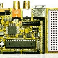
Chameleon-AVR Nurve Networks, Chameleon-AVR Datasheet - Page 71

Chameleon-AVR
Manufacturer Part Number
Chameleon-AVR
Description
MCU, MPU & DSP Development Tools AVR8 & PROPELLER DEV SYSTEM (SBC)
Manufacturer
Nurve Networks
Datasheet
1.CHAMELEON-AVR.pdf
(268 pages)
Specifications of Chameleon-AVR
Processor To Be Evaluated
AVR 328P
Data Bus Width
8 bit
Interface Type
USB, VGA, PS/2, I2C, ISP, SPI
Operating Supply Voltage
3.3 V, 5 V
Lead Free Status / RoHS Status
Lead free / RoHS Compliant
- Current page: 71 of 268
- Download datasheet (17Mb)
So to PWM modulate a “signal” we encode the signal onto the PWM carrier by means of encoding the “information” or
analog value of the signal onto the PWM carrier by modulating the period or the duty cycle of the fixed frequency PWM
carrier. This is a VERY important concept to understand – the PWM frequency/period NEVER changes, only the duty
cycle of any particular cycle. Thus by modulating the information onto the duty cycle we can then later demodulate the
signal by integrating or averaging the PWM signal with a RC circuit and presto we have an analog voltage!
The first thing we need to do is decide what kind of waveforms we want to synthesis, remember they can be ANYTHING,
they can be periodic and simple like sine, square wave (redundant), triangle, sawtooth, noise, or even digitized speech.
But, to start simple, let’s synthesis a single sine wave. So first we need a look up table for sine wave, let’s call it
sinetable[] and assume it has 256 entries and we generate it such that a single cycle has a low of 0 and a high of 255
and is encoded in 8-bits (similar to an example in the references). Now, the algorithm is fairly simple, we need to index
thru the sine table a rate such that we complete a single cycle of our sine wave at the desired output signal frequency. As
a quick and dirty example, let’s say that we use a PWM frequency of 256 KHz and we want to play a 1 KHz sine wave,
then this means that each second there are 256,000 PWM pulses, we want to index into our table and play 1000 iterations
of our data which has a length of 256 entries, thus we need to index into our table at a rate of:
Interesting, so every cycle we simple increment a counter into the sine table and output the appropriate duty cycle in the
table lookup. This is shown in Figure 14.6. As another example, say we want to synthesis a 240 Hz signal then let’s see
what we would need:
In this case, we would increment a counter until it reached 4 then we would increment our index into our sine table. But,
this example as well as the last should bring something to your attention, there is a max frequency we can synthesis and
our signal synthesis is going to be inaccurate for anything, but integral divisors, so that’s an issue we need to address in a
moment. First, let’s look at the maximum signal frequency, if you want to play back all 256 sine samples then the
maximum “signal” frequency is always:
256,000 / (1000 * 256) = 1
256,000 / (240 * 256) = 4.16
Figure 14.6 – Indexing into a Sine look up table to synthesize a signal at a given PWM rate.
© 2009 NURVE NETWORKS LLC “Exploring the Chameleon AVR 8-Bit”
71
Related parts for Chameleon-AVR
Image
Part Number
Description
Manufacturer
Datasheet
Request
R

Part Number:
Description:
MCU, MPU & DSP Development Tools PIC24 & PROPELLER DEV SYSTEM (SBC)
Manufacturer:
Nurve Networks
Datasheet:

Part Number:
Description:
MCU, MPU & DSP Development Tools AVR8 VIDEO GAME DEV SYSTEM (SBC)
Manufacturer:
Nurve Networks

Part Number:
Description:
MCU, MPU & DSP Development Tools PIC24 VIDEO GAME DEV SYSTEM (SBC)
Manufacturer:
Nurve Networks


