Chameleon-AVR Nurve Networks, Chameleon-AVR Datasheet - Page 51
Chameleon-AVR
Manufacturer Part Number
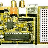
Chameleon-AVR
Description
MCU, MPU & DSP Development Tools AVR8 & PROPELLER DEV SYSTEM (SBC)
Manufacturer
Nurve Networks
Datasheet
1.CHAMELEON-AVR.pdf
(268 pages)
Specifications of Chameleon-AVR
Processor To Be Evaluated
AVR 328P
Data Bus Width
8 bit
Interface Type
USB, VGA, PS/2, I2C, ISP, SPI
Operating Supply Voltage
3.3 V, 5 V
Lead Free Status / RoHS Status
Lead free / RoHS Compliant


© 2009 NURVE NETWORKS LLC “Exploring the Chameleon AVR 8-Bit”
Now, the above algorithm to draw a frame will work, and is very simple, but it doesn’t comply with the RS-170A spec
completely. It’s missing a very important signal component called the vertical serrations in the vertical sync pulse. If you
look at the rough draft algorithm above, we have a vertical sync period, where we simply generate sync signal for 4-6
scanlines. This is fine, and will work, but you will notice an effect called “flagging” at the top of the display which is ugly. A
better approach is to continue to generate hsync pulses during the vsync. This keeps the horizontal sync timing hardware
tracking. To accomplish this, the hsync is simply inverted. Both, the hsync and vsync filters will still detect the edges of
the pulses, so the inversion doesn’t hurt anything, so both the hsync and vsync occurs and the horizontal timing circuitry
doesn’t loose sync. Now, you might ask, “why wouldn’t you always perform this inversion of the hsync during the vsync?”.
Well, the answer is that you might want to have once big continuous block of 4-6 lines that you set a single bit (sync) and
then you can do work without interruption, but the video looks quite ugly, so it’s a compromise.
In any event, considering this adjustment to our algorithm, all we have to do is generate 6 hsync pulses at the end of the
bottom overscan that are inverted, thus, this new algorithm will suffice:
11.2.5.2 Line Construction
Generating each line is a little more tricky that generating a frame since the real work must be done on each line. The
basic idea is that you must generate the video signal which controls the luma (brightness), the chroma (color), and
synchronization all within the same signal. This is accomplished by mimicking the signals you see in Figures 11.5 and
11.6. Each line consists of a total of 63.5 us where 52.6 us is actual video data and the other 10.9 us is sync and setup
data. However, you can slightly alter them if you wish. For example, if you want to make the video portion of a line 50 us
rather than 52.6 us then it will work since you can just stuff black into non-active region; however, the more you alter the
spec (especially in terms of the length of the sync and color burst) the higher the chances are that the signal will not work
on some older (or newer sets such as LCD and plasma with digital filtering).
To generate the actual video signal the Propeller chip gives you total control over the actual output voltage of the
composite video line, therefore, you program the voltages as a function of time to create each video line using the VSU
(video streaming unit). For example, each line consists of the following areas:
“Front Porch” - The spec calls for a “front porch” of 1.5 us consisting of black, therefore you would tell the Propeller
hardware to send out black, then you would delay for 1.5 us (talking into consideration the amount of time to execute the
actual instruction that turns black on).
“Sync Tip” - The next part of the spec is the horizontal sync or HSYNC, this should be approximately 4.7 us, therefore,
you would tell the video hardware to output a 0.0V for 4.7 us.
The next portion of the video signal is the “Color Burst” which consists of a pre-burst phase called the “Breezeway”, the
burst itself called the “Color Burst” and finally the post-burst called the “Back Porch”.
“Breezeway” - This part of the spec says to output black for 0.6 us.
“Color Burst” - This is the most complex part of the specification and the one that would be nearly impossible to do
without the extra hardware support of the Propeller’s VSU. In any case, we will explain how this works shortly, but for now,
you need to know that you must generate 8-10 cycles of color burst tone. This is a 3.579594 MHz “tone” signal that the TV
locks onto and uses as a phase reference for the remainder of the video line. The color of each pixel is determined by the
51
Related parts for Chameleon-AVR
Image
Part Number
Description
Manufacturer
Datasheet
Request
R

Part Number:
Description:
MCU, MPU & DSP Development Tools PIC24 & PROPELLER DEV SYSTEM (SBC)
Manufacturer:
Nurve Networks
Datasheet:

Part Number:
Description:
MCU, MPU & DSP Development Tools AVR8 VIDEO GAME DEV SYSTEM (SBC)
Manufacturer:
Nurve Networks

Part Number:
Description:
MCU, MPU & DSP Development Tools PIC24 VIDEO GAME DEV SYSTEM (SBC)
Manufacturer:
Nurve Networks