HM226-T Hendon Semiconductors, HM226-T Datasheet - Page 9
HM226-T
Manufacturer Part Number
HM226-T
Description
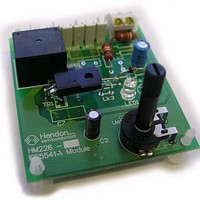
Switch Modules & Development Tools IES5541A demoboard Sensor Input Control
Manufacturer
Hendon Semiconductors
Datasheet
1.HM226-T.pdf
(15 pages)
Specifications of HM226-T
Description/function
Relay Switch Demo Board
Board Size
70 mm x 61 mm
Maximum Operating Temperature
+ 70 C
Minimum Operating Temperature
0 C
Supply Current
10 A
For Use With/related Products
IES5541A
Lead Free Status / RoHS Status
Lead free / RoHS Compliant


7.6 Thermistor/Potentiometer Failure Table
As the thermistor is remote from the HM226, there is a
possibility that these wires may either short, or may
become open circuit. Table 1 below shows the result with
such a failure. It also shows what occurs if the wiper on the
potentiometer becomes open circuit through
contamination from dust etc.
Table 1 Sensor - Potentiometer Failure Table
7.7 Accuracy
Due to the broad temperature control range, accuracy for
the typical application circuit (i.e. Figure 3 of IES5541A
data sheet) is of the order of ±20°C. This is not unusual for
a simple thermostat controlling over the range of 25°C to
+300°C. Accuracy is also affected by mains supply voltage
variations. However using the bridge input circuit
configuration (Figure 5 of IES Application Note AN004)
much more accurate control is possible.
Using thermistors chosen from the Vishay range, the
typical best thermistor accuracy is 5 % (a little over 1 °C
error/spread) although more accurate thermistors are
available (3%, 2%). With the choice of 1% resistors in the
measuring section of the circuit (R1 to R7), the total
temperature error will be less than 2 °C. In a production
batch most units will be much closer to the nominal value
(say 80% or more within 1 °C).
When a potentiometer is used to adjust to the required
temperature an error is introduced from the tolerance of
the potentiometer (usually 10 to 20%), and the designer
will allow for this by making the adjustment range wider
than that specified). However, it obviously becomes
possible to set the temperature to any desired point within
its range.
2007 Dec 11, Revision 5.0
NTC open
NTC short
Pot wiper open No heating
Pot wiper short Heat to highest
MODE
Continuous
heating
No heating
set point
HEATING
9
Protected Relay Switching Module
7.8 Digital Control
To digitally control the module, 5 extra components must
be installed. The module can then be controlled from any
5V digital logic device such as a microcontroller. The
SENS input is tied to neutral with LK1 to negate the
temprature sense network. The logic signal can then be
input through the NTC connector. The logic signal drives
transistor T1 which feeds the Cap input through D2.Rb
drains a portion of the current to protect the input. This is
exemplified in figure 5.
7.9 Relay Drive Circuit
The relay drive rectification circuit is controlled when the
IES5541A switches the SCR. For each type of relay used
diferent component values for the supply resistors and
capacitor will be needed. Further information on selecting
these values can be found in application note AN005.
7.10 RFI and EMC Compatability
The IES5541A has been designed to be especially
insensitive to interference. Even when the thermistor is
mounted remotely from the HM226 control module, the
signal is an attenuated mains voltage, and not a signal
which might provide radio frequency interference (rfi). This
is important in view of recent changes to the law with
respect to Electromagnetic Compatibility (EMC
compliance) in Australia.
In addition to appliances needing to be insensitive to
external sources of interference, these standards also
require appropriate measures to be taken to ensure no
appliances generate radio frequency interference (rfi)
beyond prescribed limits.
When controlling a resistive load the IES5541A employs
zero crossing load switching to minimise emitted rfi.
Engineering Sample Information
HM226 - L / T
Related parts for HM226-T
Image
Part Number
Description
Manufacturer
Datasheet
Request
R

Part Number:
Description:
Switch Modules & Development Tools IES5541A demoboard Logic Input Control
Manufacturer:
Hendon Semiconductors
Datasheet:

Part Number:
Description:
General Purpose Triggering Circuit
Manufacturer:
Hendon Semiconductors
Datasheet:
Part Number:
Description:
LED Drivers 1-3.5V 1W LED Boost Driver
Manufacturer:
Hendon Semiconductors
Datasheet:
Part Number:
Description:
Power Management Modules & Development Tools OM5428 demoboard
Manufacturer:
Hendon Semiconductors
Datasheet:
Part Number:
Description:
Power Management Modules & Development Tools OM5448 demoboard
Manufacturer:
Hendon Semiconductors
Part Number:
Description:
Temperature Sensor Development Tools OM1682A demoboard
Manufacturer:
Hendon Semiconductors
Datasheet:

Part Number:
Description:
Triacs Phase Controller
Manufacturer:
Hendon Semiconductors
Datasheet:

Part Number:
Description:
Buffers & Line Drivers 2.7-5.5V 4.3mA 90ns 400-1000kHz
Manufacturer:
Hendon Semiconductors
Datasheet:

Part Number:
Description:
Buffers & Line Drivers Buffered 4-Chan Bus Switch
Manufacturer:
Hendon Semiconductors
Datasheet:
Part Number:
Description:
Buffers & Line Drivers 2.7-5.5V 6.1mA 45ns 400kHz
Manufacturer:
Hendon Semiconductors
Datasheet:
Part Number:
Description:
Buffers & Line Drivers 2.7-5.5V Simple 2 Wire Buffer
Manufacturer:
Hendon Semiconductors
Datasheet:

Part Number:
Description:
Buffers & Line Drivers 2.7-5.5V 4.3mA 90ns 400-1000kHz
Manufacturer:
Hendon Semiconductors
Datasheet:
Part Number:
Description:
Buffers & Line Drivers 2.7-5.5V Simple 2 Wire Buffer
Manufacturer:
Hendon Semiconductors
Datasheet:
Part Number:
Description:
Buffers & Line Drivers 2.7-5.5V 6.1mA 45ns 400kHz
Manufacturer:
Hendon Semiconductors
Datasheet:
Part Number:
Description:
Buffers & Line Drivers 2.7-5.5V Simple 2 Wire Buffer
Manufacturer:
Hendon Semiconductors
Datasheet: