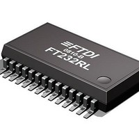
FT232RL-REEL FTDI, FT232RL-REEL Datasheet - Page 14

FT232RL-REEL
Manufacturer Part Number
FT232RL-REEL
Description
USB Interface IC USB to Serial UART Enhanced IC SSOP-28
Manufacturer
FTDI
Type
USB to UARTr
Datasheet
1.FT232RQ_R.pdf
(43 pages)
Specifications of FT232RL-REEL
Maximum Operating Temperature
85 C
Minimum Operating Temperature
-40 C
Mounting Style
SMD/SMT
Supply Current
15 mA
Operating Supply Voltage
3.3 V to 5.25 V
Package / Case
SSOP 5.3mm x 10.28mm
Description/function
USB to Serial UART Enhanced IC SSOP-28
Operating Temperature Range
- 40 C to + 85 C
Lead Free Status / RoHS Status
Lead free / RoHS Compliant
Available stocks
Company
Part Number
Manufacturer
Quantity
Price
Company:
Part Number:
FT232RL-REEL
Manufacturer:
FTDI
Quantity:
12 000
Company:
Part Number:
FT232RL-REEL
Manufacturer:
FTDI
Quantity:
120 383
Part Number:
FT232RL-REEL
Manufacturer:
FTDI
Quantity:
20 000
4
The FT232R is a USB to serial UART interface device which simplifies USB to serial designs and reduces
external component count by fully integrating an external EEPROM, USB termination resistors and an
integrated clock circuit which requires no external crystal, into the device. It has been designed to
operate efficiently with a USB host controller by using as little as possible of the total USB bandwidth
available.
4.1 Key Features
Functional Integration. Fully integrated EEPROM, USB termination resistors, clock generation, AVCC
filtering, POR and LDO regulator.
Configurable CBUS I/O Pin Options. The fully integrated EEPROM allows configuration of the Control
Bus (CBUS) functionality, signal inversion and drive strength selection. There are 5 configurable CBUS
I/O pins. These configurable options are
The CBUS pins can also be individually configured as GPIO pins, similar to asynchronous bit bang mode.
It is possible to use this mode while the UART interface is being used, thus providing up to 4 general
purpose I/O pins which are available during normal operation. An application note, AN232R-01, available
from FTDI website (www.ftdichip.com) describes this feature.
The CBUS lines can be configured with any one of these output options by setting bits in the internal
EEPROM. The device is supplied with the most commonly used pin definitions pre-programmed - see
Section 8 for details.
Asynchronous Bit Bang Mode with RD# and WR# Strobes. The FT232R supports FTDI‟s previous
chip generation bit-bang mode. In bit-bang mode, the eight UART lines can be switched from the regular
interface mode to an 8-bit general purpose I/O port. Data packets can be sent to the device and they will
be sequentially sent to the interface at a rate controlled by an internal timer (equivalent to the baud rate
pre-scaler). With the FT232R device this mode has been enhanced by outputting the internal RD# and
WR# strobes signals which can be used to allow external logic to be clocked by accesses to the bit-bang
I/O bus. This option will be described more fully in a separate application note available from FTDI
website (www.ftdichip.com).
Synchronous Bit Bang Mode. The FT232R supports synchronous bit bang mode. This mode differs from
asynchronous bit bang mode in that the interface pins are only read when the device is written to. This
makes it easier for the controlling program to measure the response to an output stimulus as the data
returned is synchronous to the output data. An application note, AN232R-01, available from FTDI website
(www.ftdichip.com) describes this feature.
FTDIChip-ID™. The FT232R also includes the new FTDIChip-ID™ security dongle feature. This
FTDIChip-ID™ feature allows a unique number to be burnt into each device during manufacture. This
number cannot be reprogrammed. This number is only readable over USB and forms a basis of a security
dongle which can be used to protect any customer application software being copied. This allows the
possibility of using the FT232R in a dongle for software licensing. Further to this, a renewable license
scheme can be implemented based on the FTDIChip-ID™ number when encrypted with other information.
This encrypted number can be stored in the user area of the FT232R internal EEPROM, and can be
decrypted, then compared with the protected FTDIChip-ID™ to verify that a license is valid. Web based
applications can be used to maintain product licensing this way. An application note, AN232R-02,
available from FTDI website (www.ftdichip.com) describes this feature.
The FT232R is capable of operating at a voltage supply between +3.3V and +5V with a nominal
operational mode current of 15mA and a nominal USB suspend mode current of 70µA. This allows greater
margin for peripheral designs to meet the USB suspend mode current limit of 2.5mA. An integrated level
converter within the UART interface allows the FT232R to interface to UART logic running at +1.8V, 2.5V,
+3.3V or +5V.
1. TXDEN - transmit enable for RS485 designs.
2. PWREN# - Power control for high power, bus powered designs.
3. TXLED# - for pulsing an LED upon transmission of data.
4. RXLED# - for pulsing an LED upon receiving data.
5. TX&RXLED# - which will pulse an LED upon transmission OR reception of data.
6. SLEEP# - indicates that the device going into USB suspend mode.
7. CLK48 / CLK24 / CLK12 / CLK6 - 48MHz, 24MHz, 12MHz, and 6MHz clock output signal
Function Description
options.
Copyright © 2010 Future Technology Devices International Limited
FT232R USB UART IC Datasheet Version 2.07
Document No.: FT_000053
Clearance No.: FTDI# 38
14


