GJM1555C1HR50BB01D Murata, GJM1555C1HR50BB01D Datasheet - Page 12
GJM1555C1HR50BB01D
Manufacturer Part Number
GJM1555C1HR50BB01D
Description
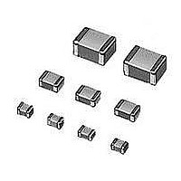
Multilayer Ceramic Capacitors (MLCC) - SMD/SMT 0402 0.5pF 50volts C0G +/-0.1pF
Manufacturer
Murata
Series
GJMr
Datasheet
1.GJM1555C1H3R3BB01D.pdf
(14 pages)
Specifications of GJM1555C1HR50BB01D
Voltage Rating
50 Volts
Operating Temperature Range
- 55 C to + 125 C
Temperature Coefficient / Code
C0G (NP0)
Product
General Type MLCCs
Dimensions
0.5 mm W x 1 mm L x 0.5 mm H
Termination Style
SMD/SMT
Capacitance
0.5 pF
Tolerance
0.1 pF
Package / Case
0402 (1005 metric)
Capacitance Tolerance
± 0.1pF
Capacitor Dielectric Type
Ceramic Multi-Layer
Capacitor Case Style
0402
No. Of Pins
2
Lead Spacing
0.3mm
Operating Temperature
RoHS Compliant
Svhc
No SVHC (15-Dec-2010)
Rohs Compliant
Yes
Lead Free Status / RoHS Status
Lead free / RoHS Compliant
Available stocks
Company
Part Number
Manufacturer
Quantity
Price
Company:

Part Number:
GJM1555C1HR50BB01D
Manufacturer:
MURATA
Quantity:
640 000
Company:
Part Number:
GJM1555C1HR50BB01D
Manufacturer:
MURATA
Quantity:
10 000


13
13
C-29-C
A p p l i c At i o n S p e c i F i c c A pA c i t o r S
High Frequency Ceramic Capacitors
GJM Soldering and Mounting
(1) For Chip Type Capacitors
FAILURE TO FOLLOW THE ABOVE CAUTIONS MAY
RESULT, WORST CASE, IN A SHORT CIRCUIT AND/OR
FUMING WHEN THE PRODUCT IS USED.
86
(1) For Chip Type Capacitors
FAILURE TO FOLLOW THE ABOVE CAUTIONS MAY
RESULT, WORST CASE, IN A SHORT CIRCUIT AND
FUMING WHEN THE PRODUCT IS USED.
86
Optimum Solder Amount when Corrections Are Made
Correction with a Soldering Iron
When sudden heat is applied to the components by
soldering iron, the mechanical strength of the
components should go down because remarkable
temperature change causes deformity inside components.
In order to prevent mechanical damage in the
components, preheating should be required for both of
the components and the PCB board. Preheating
conditions are shown in Table 3. It is required to keep
temperature differential between the soldering and the
components surface ( T) as small as possible. After
soldering, it is not allowed to cool it down rapidly.
Using a Soldering lron
The top of the solder fillet should be lower than the
thickness of components. If the solder amount is
excessively big, the risk of cracking is higher during
board bending or under any other stressful conditions.
Soldering iron ø3mm or smaller should be required. And
it is necessary to keep a distance between the soldering
iron and the components without direct touch. Thread
solder with ø0.5mm or smaller is required for soldering.
Washing
Excessive output of ultrasonic oscillation during cleaning
causes PCBs to resonate, resulting in cracked chips or
broken solder. Take note not to vibrate PCBs.
Continued from the preceding page.
Correction with a Soldering Iron
Washing
Excessive output of ultrasonic oscillation during cleaning
causes PCBs to resonate, resulting in cracked chips or
broken solder. Take note not to vibrate PCBs.
Caution
Caution
w
w
w
.
m
u
r
a
t
a
Table 3
Table 2
Part Number
GRM15/18/21/31
GJM15
GQM18/21
ERB18/21
GRM32/43/55
GNM
ERB32
Applicable for both Pb-Sn and Lead Free Solder.
Pb-Sn Solder: Sn-37Pb
Lead Free Solder: Sn-3.0Ag-0.5Cu
GJM03/15
*Applicable for both Pb-Sn and Lead Free Solder.
Pb-Sn Solder: Sn-37Pb
Lead Free Solder: Sn-3.0Ag-0.5Cu
.
Part Number
c
o
Temperature
of Soldering
350°C max.
m
Iron Tip
Temperature
Differential
T 190
T 130
Temperature
Preheating
150 C min.
3 seconds max. /
3 seconds max. /
Temperature
300 C max.
270 C max.
termination
termination
Peak
Temperature
Differential
Innovator in Electronics – 17
T 190
Up to Chip Thickness
T
Solder Amount
in Section
Atmosphere
Atmosphere
Air
Air
Air
Related parts for GJM1555C1HR50BB01D
Image
Part Number
Description
Manufacturer
Datasheet
Request
R

Part Number:
Description:
Murata Microblower 20x20 DCDC Driver Board - Samples Only
Manufacturer:
Murata
Part Number:
Description:
357-036-542-201 CARDEDGE 36POS DL .156 BLK LOPRO
Manufacturer:
Murata
Datasheet:
Part Number:
Description:
Manufacturer:
Murata
Datasheet:
Part Number:
Description:
Manufacturer:
Murata
Datasheet:
Part Number:
Description:
Manufacturer:
Murata
Datasheet:
Part Number:
Description:
Manufacturer:
Murata
Datasheet:
Part Number:
Description:
Manufacturer:
Murata
Datasheet:
Part Number:
Description:
Manufacturer:
Murata
Datasheet:
Part Number:
Description:
Manufacturer:
Murata
Datasheet:
Part Number:
Description:
BLM21BD751SN1On-Board Type (DC) EMI Suppression Filters
Manufacturer:
Murata
Datasheet:
Part Number:
Description:
BLM15AG100SN1On-Board Type (DC) EMI Suppression Filters
Manufacturer:
Murata
Datasheet:
Part Number:
Description:
NFE31PT222Z1E9On-Board Type (DC) EMI Suppression Filters
Manufacturer:
Murata
Datasheet:
Part Number:
Description:
Chip Coil
Manufacturer:
Murata
Datasheet:
Part Number:
Description:
Chip Coil
Manufacturer:
Murata
Datasheet: