GJM1555C1HR50BB01D Murata, GJM1555C1HR50BB01D Datasheet - Page 5
GJM1555C1HR50BB01D
Manufacturer Part Number
GJM1555C1HR50BB01D
Description
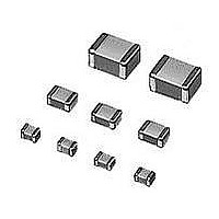
Multilayer Ceramic Capacitors (MLCC) - SMD/SMT 0402 0.5pF 50volts C0G +/-0.1pF
Manufacturer
Murata
Series
GJMr
Datasheet
1.GJM1555C1H3R3BB01D.pdf
(14 pages)
Specifications of GJM1555C1HR50BB01D
Voltage Rating
50 Volts
Operating Temperature Range
- 55 C to + 125 C
Temperature Coefficient / Code
C0G (NP0)
Product
General Type MLCCs
Dimensions
0.5 mm W x 1 mm L x 0.5 mm H
Termination Style
SMD/SMT
Capacitance
0.5 pF
Tolerance
0.1 pF
Package / Case
0402 (1005 metric)
Capacitance Tolerance
± 0.1pF
Capacitor Dielectric Type
Ceramic Multi-Layer
Capacitor Case Style
0402
No. Of Pins
2
Lead Spacing
0.3mm
Operating Temperature
RoHS Compliant
Svhc
No SVHC (15-Dec-2010)
Rohs Compliant
Yes
Lead Free Status / RoHS Status
Lead free / RoHS Compliant
Available stocks
Company
Part Number
Manufacturer
Quantity
Price
Company:

Part Number:
GJM1555C1HR50BB01D
Manufacturer:
MURATA
Quantity:
640 000
Company:
Part Number:
GJM1555C1HR50BB01D
Manufacturer:
MURATA
Quantity:
10 000


10 – Innovator in Electronics
A p p l i c At i o n S p e c i F i c c A pA c i t o r S
High Frequency Ceramic Capacitors
GJM Specifications and Test Methods
Item
Operating Temperature
Appearance
Dimension
Dielectric Strength
Insulation Resistance
Q
Adhesive Strength of
Termination
Vibration Resistance
Deflection
Solderability of Termination
Resistance to Soldering Heat
Temperature Cycle
Humidity Steady State
Humidity Load
Specifications and Test Methods
Capacitance
Temperature
Characteristics
Temperature Coefficent:
Within the specified tolerance. (Table A-1)
Capacitance Change: Within ±0.2% or ±0.05pF
(Whichever is larger)
Specifications
-55 C to 125 C
No defects or abnormalities.
Within the specified dimensions.
No defects or abnormalities.
More than 10,000M or 500 ·F
(Whichever is smaller)
30pFmin.: Q
30pFmax.: Q
C: Nominal Capacitance(pF)
No removal of the terminations or other defect should
occur.
Appearance: No defects or abnormalities.
Capacitance: Within the specified tolerance.
30pFmin.: Q
30pFmax.: Q
C: Nominal Capacitance(pF)
No crack or marked defect should occur.
75% of the terminations are to be soldered evenly
and continuously.
Appearance: No marking defects.
Capacitance Change: Within ±2.5% or
± 0.25 pF (Whichever is larger)
30pFmin.: Q
30pFmax.: Q
C: Nominal Capacitance(pF)
Appearance: No marking defects.
Capacitance Change: Within ±2.5% or
± 0.25 pF (Whichever is larger)
30pFmin.: Q
30pFmax.: Q
C: Nominal Capacitance (pF)
Appearance: No marking defects.
Capacitance Change: Within ±5% or
± 0.5pF (Whichever is larger)
30pF and over: Q
10pF and over, 30pF and below: Q 275+5C/2
10pF and below: Q
C: Nominal Capacitance (pF)
Appearance: No marking defects.
Capacitance Change: Within ±7.5% or ±0.75pF
(Whichever is larger)
1000
1000
1000
1000
400+20C
400+20C
400+20C
400+20C
w
350
200+10C
w
w
.
m
u
r
a
t
Test Methods
Reference temperature: 25 C
Visual inspection.
Using calipers.
300% of the rated voltage
DC voltage not exceeding the rated voltage at 25°C
and 75%RH max. and within 2 minutes of charging.
Frequency 1±0.1MHz
Voltage 0.5 to 5Vrms
Solder the capacitor to the test jig (glass epoxy
board) shown in Fig.1a using a eutectic solder. Then
apply 5N* force in parallel with the test jig for
10±1sec. *2N(GJM03)
The frequency range, from 10 to 55Hz and return to
10Hz, should be traversed in approximately 1 minute.
This motion should be applied for a period of 2 hours
in each 3 mutually perpendicular directions (total of 6
hours).
Flexure:1mm
Immerse in eutectic solder solution for 2±0.5 seconds
at 230±5°C or Sn-3.0Ag-0.5Cu solder solution for
2±0.5 seconds at 245±5°C .
Immerse the capacitor in a eutectic solder solution or
Sn-3.0 Ag–0.5Cu solder solution at 270±5°C for
10±0.5 seconds. Let sit at room temperature for 24±2
hours.
−55°C to 125°C Five cycles
40±2°C and 90 to 95% humiduty for 500±12 hours.
Apply the rated voltage at 40±2°C and 90 to 95%
The capacitance change should be measured after
5 min. at each specified temperature stage. The
temperature coefficient is determined using the
capacitance measured in step 3 as a reference.
When cycling the temperature sequentially from step 1
through 5 the capacitance should be within the
specified tolerance for the temperature coefficient and
capacitance change as in Table A-1. The capacitance
drift is calculated by dividing the differences between
the maximum and minimum measured values in steps
1, 3 and 5 by the cap. value in step 3.
Step
a
1
2
3
4
5
.
c
o
m
Temperature ( C)
125 3
-55 3
25 2
25 2
25 2
GJM Series
C-29-C
Related parts for GJM1555C1HR50BB01D
Image
Part Number
Description
Manufacturer
Datasheet
Request
R

Part Number:
Description:
Murata Microblower 20x20 DCDC Driver Board - Samples Only
Manufacturer:
Murata
Part Number:
Description:
357-036-542-201 CARDEDGE 36POS DL .156 BLK LOPRO
Manufacturer:
Murata
Datasheet:
Part Number:
Description:
Manufacturer:
Murata
Datasheet:
Part Number:
Description:
Manufacturer:
Murata
Datasheet:
Part Number:
Description:
Manufacturer:
Murata
Datasheet:
Part Number:
Description:
Manufacturer:
Murata
Datasheet:
Part Number:
Description:
Manufacturer:
Murata
Datasheet:
Part Number:
Description:
Manufacturer:
Murata
Datasheet:
Part Number:
Description:
Manufacturer:
Murata
Datasheet:
Part Number:
Description:
BLM21BD751SN1On-Board Type (DC) EMI Suppression Filters
Manufacturer:
Murata
Datasheet:
Part Number:
Description:
BLM15AG100SN1On-Board Type (DC) EMI Suppression Filters
Manufacturer:
Murata
Datasheet:
Part Number:
Description:
NFE31PT222Z1E9On-Board Type (DC) EMI Suppression Filters
Manufacturer:
Murata
Datasheet:
Part Number:
Description:
Chip Coil
Manufacturer:
Murata
Datasheet:
Part Number:
Description:
Chip Coil
Manufacturer:
Murata
Datasheet: