PKM2515EPI Ericsson Power Modules, PKM2515EPI Datasheet - Page 20
PKM2515EPI
Manufacturer Part Number
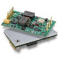
PKM2515EPI
Description
DC/DC Converters & Regulators 15Vdc 3.3A Isolated Input 18-36V 50W
Manufacturer
Ericsson Power Modules
Series
PKM-Er
Datasheet
1.PKM2515EPI.pdf
(25 pages)
Specifications of PKM2515EPI
Output Power
50 W
Input Voltage Range
18 V to 36 V
Number Of Outputs
1
Output Voltage (channel 1)
15 V
Output Current (channel 1)
3.3 A
Package / Case Size
Quarter Brick
Output Type
Isolated
Lead Free Status / RoHS Status
Lead free / RoHS Compliant
Available stocks
Company
Part Number
Manufacturer
Quantity
Price
Company:

Part Number:
PKM2515EPI
Manufacturer:
Ericsson
Quantity:
12 000
Company:
Part Number:
PKM2515EPIHS
Manufacturer:
Ericsson
Quantity:
12 000
Company:
Part Number:
PKM2515EPIPLA
Manufacturer:
POWEREX
Quantity:
1 000


EMC Specification
The conducted EMI measurement was performed using a
module placed directly on the test bench .
The fundamental switching frequency is 180 kHz for
PKM2510E PI @ V
External filter (class B)
Required external input filter in order to meet class B in
EN 55022, CISPR 22 and FCC part 15J .
PKM 2510 E PI without filter
PKM 2510 E PI with filter
PKM 2000E PI Datasheet
Conducted EMI Input terminal value (typ)
0.68uF
PO422(Pulse)
768uH
I
= 27V, I
0.68uF
O
= (0 .1 . . .1 .0) x I
3.9nF
3.9nF
47uH
0.68uF
220uF
O
max .
+
+
-
DC/DC
0
Test set-up.
Layout Recommendation
The radiated EMI performance of the DC/DC converter
will be optimised by including a ground plane in the PCB
area under the DC/DC converter . This approach will re-
turn switching noise to ground as directly as possible, with
improvements to both emissions and susceptibility . It is also
important to consider the stand-off of the PKM 2000E series
DC/DC converter . If one ground trace is used, it should be
connected to the input return . Alternatively, two ground
traces may be used, with the trace under the input side of
the DC/DC converter connected to the input return and the
trace under the output side of the DC/DC converter con-
nected to the output return . Make sure to use appropriate
safety isolation spacing between these two return traces .
The use of two traces as described will provide the capabil-
ity of routing the input noise and output noise back to their
respective returns .
Output ripple and noise
The circuit below has been used for the ripple and noise
measurements on the PKM 2000E Series DC/DC converters .
DC
Power
Source
* Conductor from Vout to capacitors = 50mm [1.97in]
+
-
50 ohm input
in
in
5µH 50Ω
5µH 50Ω
LISN
LISN
+Sense
-Sense
+Vout
Output ripple and noise test setup
-Vout
Trim
rcvr
rcvr
EMC
Reciver
EN/LZT 146 050 R4A © Ericsson Power Modules, March 2007
out
out
1 m Twisted Pair
Optional Connection
to Earth Ground
50 ohm temination
Ceramic
Capacitor
0.1uF
Filter
(if used)
Computer
Tantalum
Capacitor
Printed Circuit Board
+
10uF
Power Module
BNC
Connector
to Scope
Load
Resistive
Load
Related parts for PKM2515EPI
Image
Part Number
Description
Manufacturer
Datasheet
Request
R

Part Number:
Description:
37.5-150W DC/DC POWER MODULES
Manufacturer:
Ericsson Power Modules
Part Number:
Description:
DC/DC Power Supply Dual-OUT 3.3V/5V 9.6A/6.4A 40W 10-Pin
Manufacturer:
Ericsson Power Modules
Part Number:
Description:
DC/DC Power Supply Single-OUT 3.3V 20A 66W 8-Pin Quarter-Brick
Manufacturer:
Ericsson Power Modules
Datasheet:
Part Number:
Description:
DC/DC Power Supply Single-OUT 1.8V 50A 90W 11-Pin
Manufacturer:
Ericsson Power Modules
Part Number:
Description:
Module DC-DC 1-OUT 1.8V 30A 54W 9-Pin
Manufacturer:
Ericsson Power Modules

Part Number:
Description:
Module DC-DC 1-OUT 1.8V 60A 108W 11-Pin Half-Brick
Manufacturer:
Ericsson Power Modules
Datasheet:

Part Number:
Description:
Module DC-DC 1-OUT 12V 25A 300W 11-Pin Half-Brick
Manufacturer:
Ericsson Power Modules
Part Number:
Description:
Module DC-DC 1-OUT 5V 20A 100W Quarter-Brick
Manufacturer:
Ericsson Power Modules

Part Number:
Description:
Module DC-DC 1-OUT 12V 6A 72W 8-Pin 1/8-Brick
Manufacturer:
Ericsson Power Modules
Datasheet:
Part Number:
Description:
Module DC-DC 1-OUT 5.05V 2A 10W 18-Pin SMD
Manufacturer:
Ericsson Power Modules
Part Number:
Description:
Manufacturer:
Ericsson Power Modules
Datasheet:

Part Number:
Description:
Module DC-DC 1-OUT 5V 60A 300W 11-Pin Half-Brick Tray
Manufacturer:
Ericsson Power Modules
Part Number:
Description:
Module DC-DC 1-OUT 12V 1A 12W 18-Pin
Manufacturer:
Ericsson Power Modules
Datasheet:
Part Number:
Description:
Module DC-DC 2-OUT 12V/-12V 0.25A 6W 18-Pin SMD
Manufacturer:
Ericsson Power Modules
Part Number:
Description:
Module DC-DC 1-OUT 28V 11A 310W 11-Pin Half-Brick Tray
Manufacturer:
Ericsson Power Modules
Datasheet: