PKM2515EPI Ericsson Power Modules, PKM2515EPI Datasheet - Page 21
PKM2515EPI
Manufacturer Part Number
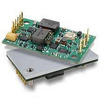
PKM2515EPI
Description
DC/DC Converters & Regulators 15Vdc 3.3A Isolated Input 18-36V 50W
Manufacturer
Ericsson Power Modules
Series
PKM-Er
Datasheet
1.PKM2515EPI.pdf
(25 pages)
Specifications of PKM2515EPI
Output Power
50 W
Input Voltage Range
18 V to 36 V
Number Of Outputs
1
Output Voltage (channel 1)
15 V
Output Current (channel 1)
3.3 A
Package / Case Size
Quarter Brick
Output Type
Isolated
Lead Free Status / RoHS Status
Lead free / RoHS Compliant
Available stocks
Company
Part Number
Manufacturer
Quantity
Price
Company:

Part Number:
PKM2515EPI
Manufacturer:
Ericsson
Quantity:
12 000
Company:
Part Number:
PKM2515EPIHS
Manufacturer:
Ericsson
Quantity:
12 000
Company:
Part Number:
PKM2515EPIPLA
Manufacturer:
POWEREX
Quantity:
1 000


Operating Information
Input Voltage
The input voltage range 18…36Vdc meets typical
requirements in 24 V DC systems used in communications,
avionics, industrial and medical equipment . At input voltages
exceeding 36V, the power loss will be higher than at normal
input voltage and T
+110°C . The absolute maximum continuous input voltage is
40Vdc .
Turn-Off Input Voltage
The PKM 2000E Series DC/DC converters monitor the input
voltage and will turn on and turn off at predetermined levels .
The minimum hysteresis between turn on and turn off input
voltage is 2V where the turn on input voltage is the highest .
Remote Control (RC)
pull up resistor to + In . The needed maximum sink current
is 1mA . When the RC pin is left open, the voltage generated
on the RC pin is 3 .5 - 6 V . The maximum allowable leakage
current of the switch is 50 µA .
The standard converter is provided with “negative logic”
remote control and the converter will be off until the RC
pin is connected to the - In . To turn on the converter the
voltage between RC pin and - In should be less than 1V .
To turn off the converter the RC pin should be left open, or
connected to a voltage higher than 4 V referenced to - In . In
situations where it is desired to have the converter to power
up automatically without the need for control signals or a
switch, the RC pin can be wired directly to - In .
The second option is “positive logic” remote control, which
can be ordered by adding the suffix “P” to the end of the
part number . The converter will turn on when the input
voltage is applied with the RC pin open . Turn off is achieved
by connecting the RC pin to the - In . To ensure safe turn
off the voltage difference between RC pin and the - In pin
shall be less than 1V . The converter will restart automatically
when this connection is opened .
PKM 2000E PI Datasheet
Circuit configuration
for RC function
RC
+In
-In
ref
must be limited to absolute max
The PKM 2000E Series DC/DC
converters have a remote control
function referenced to the primary
side (- In), with negative and positive
logic options available . The RC
function allows the converter to be
turned on/off by an external device
like a semiconductor or mechanical
switch . The RC pin has an internal
1
Remote Sense
Output Voltage Adjust (V
All PKM 2000E Series DC/DC converters have an Output
Voltage adjust pin (Vadj) . This pin can be used to adjust
the output voltage above or below Output voltage initial
setting . When increasing the output voltage, the voltage at
the output pins (including any remote sense offset) must
be kept below the overvoltage trip point, to prevent the
converter from shut down . Also note that at increased output
voltages the maximum power rating of the converter remains
the same, and the output current capability will decrease
correspondingly . To decrease the output voltage the resistor
should be connected between Vadj pin and –Sense pin .
To increase the voltage the resistor should be connected
between Vadj pin and +Sense pin . The resistor value of the
Output voltage adjust function is according to information
given under the output section .
All PKM 2000E Series DC/DC converters have remote sense
that can be used to compensate for moderate amounts of
resistance in the distribution system and allow for voltage
regulation at the load or other selected point . The remote
sense lines will carry very little current and do not need a
large cross sectional area . However, the sense lines on the
PCB should be located close to a ground trace or ground
plane . In a discrete wiring situation, the use of twisted pair
wires or other technique to reduce noise susceptibility
is highly recommended . The remote sense circuitry will
compensate for up to 10% voltage drop between the sense
voltage and the voltage at the output pins . The output
voltage and the remote sense voltage offset must be less
than the minimum over voltage trip point . If the remote sense
is not needed the –Sense should be connected to –Out and
+Sense should be connected to +Out .
+Out
+Sense
V adj
-Sense
-Out
Decrease
Circuit configuration for output voltage adjust
R adj
EN/LZT 146 050 R4A © Ericsson Power Modules, March 2007
Load
adj
)
+Out
+Sense
V adj
-Sense
-Out
Increase
R adj
Load
Related parts for PKM2515EPI
Image
Part Number
Description
Manufacturer
Datasheet
Request
R

Part Number:
Description:
37.5-150W DC/DC POWER MODULES
Manufacturer:
Ericsson Power Modules
Part Number:
Description:
DC/DC Power Supply Dual-OUT 3.3V/5V 9.6A/6.4A 40W 10-Pin
Manufacturer:
Ericsson Power Modules
Part Number:
Description:
DC/DC Power Supply Single-OUT 3.3V 20A 66W 8-Pin Quarter-Brick
Manufacturer:
Ericsson Power Modules
Datasheet:
Part Number:
Description:
DC/DC Power Supply Single-OUT 1.8V 50A 90W 11-Pin
Manufacturer:
Ericsson Power Modules
Part Number:
Description:
Module DC-DC 1-OUT 1.8V 30A 54W 9-Pin
Manufacturer:
Ericsson Power Modules

Part Number:
Description:
Module DC-DC 1-OUT 1.8V 60A 108W 11-Pin Half-Brick
Manufacturer:
Ericsson Power Modules
Datasheet:

Part Number:
Description:
Module DC-DC 1-OUT 12V 25A 300W 11-Pin Half-Brick
Manufacturer:
Ericsson Power Modules
Part Number:
Description:
Module DC-DC 1-OUT 5V 20A 100W Quarter-Brick
Manufacturer:
Ericsson Power Modules

Part Number:
Description:
Module DC-DC 1-OUT 12V 6A 72W 8-Pin 1/8-Brick
Manufacturer:
Ericsson Power Modules
Datasheet:
Part Number:
Description:
Module DC-DC 1-OUT 5.05V 2A 10W 18-Pin SMD
Manufacturer:
Ericsson Power Modules
Part Number:
Description:
Manufacturer:
Ericsson Power Modules
Datasheet:

Part Number:
Description:
Module DC-DC 1-OUT 5V 60A 300W 11-Pin Half-Brick Tray
Manufacturer:
Ericsson Power Modules
Part Number:
Description:
Module DC-DC 1-OUT 12V 1A 12W 18-Pin
Manufacturer:
Ericsson Power Modules
Datasheet:
Part Number:
Description:
Module DC-DC 2-OUT 12V/-12V 0.25A 6W 18-Pin SMD
Manufacturer:
Ericsson Power Modules
Part Number:
Description:
Module DC-DC 1-OUT 28V 11A 310W 11-Pin Half-Brick Tray
Manufacturer:
Ericsson Power Modules
Datasheet: