PKM2515EPI Ericsson Power Modules, PKM2515EPI Datasheet - Page 22
PKM2515EPI
Manufacturer Part Number
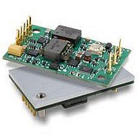
PKM2515EPI
Description
DC/DC Converters & Regulators 15Vdc 3.3A Isolated Input 18-36V 50W
Manufacturer
Ericsson Power Modules
Series
PKM-Er
Datasheet
1.PKM2515EPI.pdf
(25 pages)
Specifications of PKM2515EPI
Output Power
50 W
Input Voltage Range
18 V to 36 V
Number Of Outputs
1
Output Voltage (channel 1)
15 V
Output Current (channel 1)
3.3 A
Package / Case Size
Quarter Brick
Output Type
Isolated
Lead Free Status / RoHS Status
Lead free / RoHS Compliant
Available stocks
Company
Part Number
Manufacturer
Quantity
Price
Company:

Part Number:
PKM2515EPI
Manufacturer:
Ericsson
Quantity:
12 000
Company:
Part Number:
PKM2515EPIHS
Manufacturer:
Ericsson
Quantity:
12 000
Company:
Part Number:
PKM2515EPIPLA
Manufacturer:
POWEREX
Quantity:
1 000


Over Temperature Protection (OTP)
The PKM 2000E Series DC/DC converters are protected
from thermal overload by an internal over temperature
shutdown circuit . When the PCB temperature adjacent to
the PWM control circuit exceeds 120 ºC the converter will
shut down immediately . The converter will make continuos
attempts to start up (non-latching mode) and resume normal
operation automatically when the temperature has dropped
>10ºC below the temperature threshold .
Operating Information
PKM 2000E PI Datasheet
Current Limit Protection
The PKM 2000E Series DC/DC converters include current
limiting circuitry that allows them to withstand continuous
overloads or short circuit conditions on the output . The out-
put voltage will decrease towards zero for output currents in
excess of max output current (Iomax) .
The converter will resume normal operation after removal
of the overload . The load distribution system should be
designed to carry the maximum output short circuit current
specified .
Over Voltage Protection (OVP)
The PKM 2000E Series DC/DC converters have output over-
voltage protection . In the event of an overvoltage condition,
the converter will shut down immediately . The converter will
make continuous attempts to start up (non-latching mode)
and resume normal operation automatically .
Input And Output Impedance
The impedance of both the power source and the load will
interact with the impedance of the DC/DC converter . It is
most important to have a ratio between L and C as low as
possible, i .e . a low characteristic impedance, both at the in-
put and output, as the converters have a low energy storage
capability . The PKM 2000E Series DC/DC converters have
been designed to be completely stable without the need
for external capacitors on the input or the output circuits .
The performance in some applications can be enhanced by
addition of external capacitance as described under maxi-
mum capacitive load . If the distribution of the input voltage
source to the converter contains significant inductance, the
addition of a 100µF capacitor across the input of the con-
verter will help insure stability . This capacitor is not required
when powering the DC/DC converter from a low impedance
source with short, low inductance, input power leads .
Maximum Capacitive Load
Parallel Operation
The PKM 2000E Series DC/DC converters can be paralleled
for redundancy if external o-ring diodes are used in series
with the outputs . It is not recommended to parallel the PKM
2000E Series DC/DC converters for increased power without
using external current sharing circuits .
When powering loads with significant dynamic current
requirements, the voltage regulation at the load can be
improved by addition of decoupling capacitance at the load .
The most affective technique is to locate low ESR ceramic
capacitors as close to the load as possible, using several
capacitors to lower the effective ESR . These ceramic ca-
pacitors will handle short duration high-frequency compo-
nents of dynamic load changes . In addition, higher values of
electrolytic capacitors should be used to handle the mid-fre-
quency components . It is equally important to use good de-
sign practise when configuring the DC distribution system .
Low resistance and low inductance PCB (printed circuit
board) layouts and cabling should be used . Remember that
when using remote sensing, all resistance, inductance and
capacitance of the distribution system is within the feed-
back loop of the converter . This can affect on the convert-
ers compensation and the resulting stability and dynamic
response performance . As a “rule of thumb”, 100µF/A of
output current can be used without any additional analysis .
For example with a 25A converter, values of decoupling
capacitance up to 2500 µF can be used without regard to
stability . With larger values of capacitance, the load transient
recovery time can exceed the specified value . As much of
the capacitance as possible should be outside the remote
sensing loop and close to the load . The absolute maximum
value of output capacitance is 10 000 µF . For values larger
than this, please contact your local Ericsson Power Modules
representative .
EN/LZT 146 050 R4A © Ericsson Power Modules, March 2007
Related parts for PKM2515EPI
Image
Part Number
Description
Manufacturer
Datasheet
Request
R

Part Number:
Description:
37.5-150W DC/DC POWER MODULES
Manufacturer:
Ericsson Power Modules
Part Number:
Description:
DC/DC Power Supply Dual-OUT 3.3V/5V 9.6A/6.4A 40W 10-Pin
Manufacturer:
Ericsson Power Modules
Part Number:
Description:
DC/DC Power Supply Single-OUT 3.3V 20A 66W 8-Pin Quarter-Brick
Manufacturer:
Ericsson Power Modules
Datasheet:
Part Number:
Description:
DC/DC Power Supply Single-OUT 1.8V 50A 90W 11-Pin
Manufacturer:
Ericsson Power Modules
Part Number:
Description:
Module DC-DC 1-OUT 1.8V 30A 54W 9-Pin
Manufacturer:
Ericsson Power Modules

Part Number:
Description:
Module DC-DC 1-OUT 1.8V 60A 108W 11-Pin Half-Brick
Manufacturer:
Ericsson Power Modules
Datasheet:

Part Number:
Description:
Module DC-DC 1-OUT 12V 25A 300W 11-Pin Half-Brick
Manufacturer:
Ericsson Power Modules
Part Number:
Description:
Module DC-DC 1-OUT 5V 20A 100W Quarter-Brick
Manufacturer:
Ericsson Power Modules

Part Number:
Description:
Module DC-DC 1-OUT 12V 6A 72W 8-Pin 1/8-Brick
Manufacturer:
Ericsson Power Modules
Datasheet:
Part Number:
Description:
Module DC-DC 1-OUT 5.05V 2A 10W 18-Pin SMD
Manufacturer:
Ericsson Power Modules
Part Number:
Description:
Manufacturer:
Ericsson Power Modules
Datasheet:

Part Number:
Description:
Module DC-DC 1-OUT 5V 60A 300W 11-Pin Half-Brick Tray
Manufacturer:
Ericsson Power Modules
Part Number:
Description:
Module DC-DC 1-OUT 12V 1A 12W 18-Pin
Manufacturer:
Ericsson Power Modules
Datasheet:
Part Number:
Description:
Module DC-DC 2-OUT 12V/-12V 0.25A 6W 18-Pin SMD
Manufacturer:
Ericsson Power Modules
Part Number:
Description:
Module DC-DC 1-OUT 28V 11A 310W 11-Pin Half-Brick Tray
Manufacturer:
Ericsson Power Modules
Datasheet: