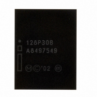
PC28F128P30B85A NUMONYX, PC28F128P30B85A Datasheet - Page 70

PC28F128P30B85A
Manufacturer Part Number
PC28F128P30B85A
Description
IC FLASH 128MBIT 85NS 64EZBGA
Manufacturer
NUMONYX
Series
StrataFlash™r
Datasheet
1.RD48F4400P0VBQEJ.pdf
(97 pages)
Specifications of PC28F128P30B85A
Format - Memory
FLASH
Memory Type
FLASH
Memory Size
128M (8Mx16)
Speed
85ns
Interface
Parallel
Voltage - Supply
1.7 V ~ 2 V
Operating Temperature
-40°C ~ 85°C
Package / Case
64-TBGA
Lead Free Status / RoHS Status
Lead free / RoHS Compliant
Other names
873877
873877
PC28F128P30B85
PC28F128P30B85 873877
873877
PC28F128P30B85
PC28F128P30B85 873877
Available stocks
Company
Part Number
Manufacturer
Quantity
Price
Company:
Part Number:
PC28F128P30B85A
Manufacturer:
Micron Technology Inc
Quantity:
10 000
Part Number:
PC28F128P30B85A
Manufacturer:
MICRON/美光
Quantity:
20 000
Appendix A Supplemental Reference Information
A.1
A.1.1
Table 37: Summary of CFI Structure Output as a Function of Device and Mode
Datasheet
70
Common Flash Interface Tables
The Common Flash Interface (CFI) is part of an overall specification for multiple
command-set and control-interface descriptions. This appendix describes the database
structure containing the data returned by a read operation after issuing the Read CFI
command (see
this database structure to obtain information about the flash device, such as block size,
density, bus width, and electrical specifications. The system software will then know
which command set(s) to use to properly perform flash writes, block erases, reads and
otherwise control the flash device.
CFI Structure Output
The CFI database allows system software to obtain information for controlling the flash
device. This section describes the device’s CFI-compliant interface that allows access to
CFI data.
CFI data are presented on the lowest-order data outputs (DQ
offset value is the address relative to the maximum bus width supported by the device.
On this family of devices, the CFI table device starting address is a 10h, which is a word
address for x16 devices.
For a word-wide (x16) device, the first two CFI-structure bytes, ASCII “Q” and “R,”
appear on the low byte at word addresses 10h and 11h. This CFI-compliant device
outputs 00h data on upper bytes. The device outputs ASCII “Q” in the low byte (DQ
and 00h in the high byte (DQ
At CFI addresses containing two or more bytes of information, the least significant data
byte is presented at the lower address, and the most significant data byte is presented
at the higher address.
In all of the following tables, addresses and data are represented in hexadecimal
notation, so the “h” suffix has been dropped. In addition, since the upper byte of word-
wide devices is always “00h,” the leading “00” has been dropped from the table
notation and only the lower byte value is shown. Any x16 device outputs can be
assumed to have 00h on the upper byte in this mode.
Device Addresses
Section 6.0, “Command Set” on page
Device
15-8
).
24). System software can parse
7-0
00010:
00011:
00012:
Offset
Hex
) only. The numerical
Code
Hex
51
52
59
ASCII
Value
August 2008
"Q"
"R"
"Y"
306666-12
7-0
P30
)


