VNCLO-MB1A FTDI, Future Technology Devices International Ltd, VNCLO-MB1A Datasheet - Page 7
VNCLO-MB1A
Manufacturer Part Number
VNCLO-MB1A
Description
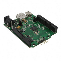
MOD VINCULO VNC2 MOTHERBOARD
Manufacturer
FTDI, Future Technology Devices International Ltd
Series
Vinculo, Vinculum-IIr
Specifications of VNCLO-MB1A
Main Purpose
Interface, USB 2.0 Host/Controller, Arduino Shield Compatible
Embedded
Yes, MCU, 16-Bit
Utilized Ic / Part
VNC2-64Q
Primary Attributes
9V Input Power Supply, 5V Operating Voltage
Secondary Attributes
2 USB Ports
Lead Free Status / RoHS Status
Lead free / RoHS Compliant
Other names
768-1088-
768-1088-
768-1088-


Document Reference No.: FT_000327
Vinco Development Module Datasheet Version 2.0
Clearance No.: FTDI#173
2
Functionality
2.1 Power
The Vinco requires +5V for the USB host ports to power USB devices from the module. This is further
regulated to +3.3V for VNC2.
A +9V/1A DC supply is also available which can be used as an AC-DC adapter (wall-wart). The +9V is
regulated to +5V and +3V3 on the Vinco module.
As an alternative to the AC-DC adapter the on board regulators can be taken out of circuit with jumpers
to allow the +5V from a USB host port to power the module. Care should be taken with this approach as
a USB host port can only provide a maximum of 500mA, which must power the Vinco and potentially any
devices connected to the Vinco.
The +5V and +3V3 supplies may also be accessed on the J1 header pins.
VNC2 requires between 8 and 24mA depending on the clock speed at which the VNC2 core is running.
2.2 Input/Output
Due to the flexibility of the VNC2 IC the actual definition of each pin is not fixed. The firmware developed
for any application can use the VNC2 IO Mux to route a signal, e.g. UART TXD, to a range of IO pins. An
IOMux utility built into the free tool chain development environment, IDE, allows the developer to define
the IO from a GUI interface. The utility will then convert the users IO selection into C code to be included
as part of the project firmware...
There are 38 configurable IO pins available to the user, 8 of which are reserved for connecting to the
onboard ADC device. The other 30 pins may be used for GPIO, UART, SPI or FIFO connectivity depending
on the interface of the shield designed to connect to the Vinco module.
There are 2 USB ports on the Vinco. The firmware will determine if the port is configured for USB host
operation or USB device operation.
2.3 LEDs & PWREN#
There are 3 LEDs and one power control signal, PWREN# on Vinco.
LED1 is driven by the VNC2-64Q IC depending on which firmware is loaded. It may be used to indicate
traffic on the USB slave port connected via CN3. LED1 is connected to the VNC2-64Q IC on pin 39.
Configure this pin for a GPIO output in order to use this LED.
LED2 is driven by the VNC2-64Q IC depending on which firmware is loaded. It may be used to indicate
traffic on the USB host port connected via CN2.LED2 is connected to the VNC2-64Q IC on pin 40.
Configure this pin for a GPIO output in order to use this LED.
LED3 is driven by the 3V3 supply that also powers the VNC2-64Q IC. It will indicate when the Vinco
module is powered.
PWREN# is a signal that controls the power output to the USB Host connector, CN2. PWREN# is
connected to the VNC2-64Q IC on pin 41. Configure this pin for a GPIO output in order to make power
available at CN2 for USB peripherals.
Copyright © 2010-2011 Future Technology Devices International Limited
3
Related parts for VNCLO-MB1A
Image
Part Number
Description
Manufacturer
Datasheet
Request
R

Part Number:
Description:
POWER SUPPLY FOR VNCLO-MB1A USA
Manufacturer:
FTDI, Future Technology Devices International Ltd
Datasheet:

Part Number:
Description:
POWER SUPPLY FOR VNCLO-MB1A EU
Manufacturer:
FTDI, Future Technology Devices International Ltd
Datasheet:
Part Number:
Description:
POWER SUPPLY FOR VNCLO-MB1A UK
Manufacturer:
FTDI, Future Technology Devices International Ltd
Datasheet:

Part Number:
Description:
MOD VINCULO PIGGYBACK BOARD
Manufacturer:
FTDI, Future Technology Devices International Ltd
Datasheet:

Part Number:
Description:
MOD VINCULO W/VNC2 DEBUG MOD
Manufacturer:
FTDI, Future Technology Devices International Ltd
Datasheet:

Part Number:
Description:
IC USB TO SERIAL UART 32-QFN
Manufacturer:
FTDI, Future Technology Devices International Ltd

Part Number:
Description:
IC USB HOST CTLR VINCULUM 48LQFP
Manufacturer:
FTDI, Future Technology Devices International Ltd
Datasheet:

Part Number:
Description:
IC USB HOST VINCULUM-II 32QFN
Manufacturer:
FTDI, Future Technology Devices International Ltd
Datasheet:
Part Number:
Description:
IC USB HOST VINCULUM-II 32LQFN
Manufacturer:
FTDI, Future Technology Devices International Ltd
Datasheet:
Part Number:
Description:
IC USB HOST VINCULUM-II 48QFN
Manufacturer:
FTDI, Future Technology Devices International Ltd
Datasheet:
Part Number:
Description:
IC USB HOST VINCULUM-II 32LQFN
Manufacturer:
FTDI, Future Technology Devices International Ltd
Datasheet:
Part Number:
Description:
IC USB HOST VINCULUM-II 32QFN
Manufacturer:
FTDI, Future Technology Devices International Ltd
Datasheet:
Part Number:
Description:
IC USB HOST VINCULUM-II 48LQFP
Manufacturer:
FTDI, Future Technology Devices International Ltd
Datasheet:
Part Number:
Description:
IC USB HOST VINCULUM-II 48LQFP
Manufacturer:
FTDI, Future Technology Devices International Ltd
Datasheet:
Part Number:
Description:
IC USB HOST VINCULUM-II 48QFN
Manufacturer:
FTDI, Future Technology Devices International Ltd
Datasheet: