LMP90100EB/NOPB National Semiconductor, LMP90100EB/NOPB Datasheet
LMP90100EB/NOPB
Specifications of LMP90100EB/NOPB


Related parts for LMP90100EB/NOPB

LMP90100EB/NOPB Summary of contents
Page 1
... The LMP90100 Evaluation Board Design Kit (consisting of the LMP90100 Evaluation Board, the SPIO-4 Digital Controller Board, the Sensor AFE software, and this user’s guide) is designed to ease evaluation and design-in of National Semiconductor’s LMP90100 24-bit Fully Programmable Low Power ADC with True Continuous Background Calibration. ...
Page 2
... Figure 1 shows the connection between the LMP90100 Evaluation Board, SPIO-4 Digital Controller Board, and a personal computer with Sensor AFE software. LMP90100 can be powered using external power supplies or from the SPIO-4 board. © 2009 National Semiconductor Corporation with Sensor AFE Software User’s Guide Figure 1 – Connection Diagram Page lmp90100eb_usersguide_20101227_v23 ...
Page 3
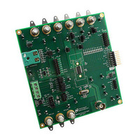
... Board Assembly Figure 2 – LMP90100 Evaluation Board Assembly © 2009 National Semiconductor Corporation LMP90100 Evaluation Board with Sensor AFE Software User’s Guide Page lmp90100eb_usersguide_20101227_v23.doc ...
Page 4
... Turn on the power supplies that are sourcing VA (J1) and VIO (J3). 4. Connect the LMP90100EB’s JP12 to SPIO-4 Board’s J6 (pins 1-16). See Figure 3. © 2009 National Semiconductor Corporation with Sensor AFE Software User’s Guide Jumper Connections Pins 1 & 2 Source VA with an external power supply Pins 1 & ...
Page 5
... Step 9: Performance - click on the “Performance” mini-tab. This tab displays the Estimated Device Performance base on the block diagram that you’ve configured, as well as the Measured System Performance if you’ve connected a board and ran the LMP90100. © 2009 National Semiconductor Corporation LMP90100 Evaluation Board with Sensor AFE Software User’s Guide Page lmp90100eb_usersguide_20101227_v23 ...
Page 6
... Under the “Stop Condition” field, select Run “1000” samples. c. Click on the “Run” button to view the output voltage results. A reading of approximately ½(VREF1) should be plotted as seen in © 2009 National Semiconductor Corporation with Sensor AFE Software User’s Guide Figure 5 - Scan Mode Settings Figure 6 ...
Page 7
... Figure 6 - Results for Example # Reading © 2009 National Semiconductor Corporation LMP90100 Evaluation Board with Sensor AFE Software User’s Guide Page lmp90100eb_usersguide_20101227_v23.doc ...
Page 8
... JP13 JP13 JP14 JP14 JP10 JP9 G. Opening the Software - follow section “9.0. Installing the Software” to install the Sensor AFE software. © 2009 National Semiconductor Corporation with Sensor AFE Software User’s Guide Figure 20 . Jumper Connections Pins 2 & 3 Pins 2 & 3 Pins 2 & 3 Pins 1 & ...
Page 9
... Step 9: Performance - click on the “Performance” mini-tab. This tab displays the Estimated Device Performance base on the block diagram that you’ve configured, as well as the Measured System Performance if you’ve connected a board and ran the LMP90100. © 2009 National Semiconductor Corporation LMP90100 Evaluation Board with Sensor AFE Software User’s Guide Page lmp90100eb_usersguide_20101227_v23 ...
Page 10
... Under the “Stop Condition” field, select Run “500” samples. d. Click on the “Run” button to view the output voltage results. A reading in the hundreds of uV should be plotted similar to Figure 9. © 2009 National Semiconductor Corporation LMP90100 Evaluation Board with Sensor AFE Software User’s Guide Figure 8 - Scan Mode Settings Page lmp90100eb_usersguide_20101227_v23 ...
Page 11
... Click on the “Run” button again to view the output voltage results. A mean output reading closer to 0V should be plotted similar to demonstrates the LMP90100 offset calibration feature. © 2009 National Semiconductor Corporation LMP90100 Evaluation Board with Sensor AFE Software User’s Guide Figure 10 ...
Page 12
... Figure 10 - Results for Shorted Input Test with Calibration © 2009 National Semiconductor Corporation LMP90100 Evaluation Board with Sensor AFE Software User’s Guide Page lmp90100eb_usersguide_20101227_v23.doc ...
Page 13
... The jumpers not mentioned in this table have to be left unconnected for this exercise. 3. SPIO-4 board is properly setup out of the box (no assembly required). Jumper JP1 JP2 JP4 JP6 JP7 JP11 © 2009 National Semiconductor Corporation with Sensor AFE Software User’s Guide J10 RLINE1 WHITE 1 RTD 2 PT-100 RRTD2 ...
Page 14
... Step 5: Set Gain – since VIN = 0.109 V at room temperature for IB1 = IB2 = 1000 uA, the maximum gain can be 16x. Click on the “FGA” block, “PGA” block, or the “Gain” slider to select the gain. © 2009 National Semiconductor Corporation with Sensor AFE Software User’s Guide Jumper Connections Pins 3 & ...
Page 15
... Device Performance base on the block diagram that you’ve configured, as well as the Measured System Performance if you’ve connected a board and ran the LMP90100. Figure 12 - Recommended LMP90100 Configuration for a PT-100 RTD Reading © 2009 National Semiconductor Corporation LMP90100 Evaluation Board with Sensor AFE Software User’s Guide Page lmp90100eb_usersguide_20101227_v23 ...
Page 16
... Under the “Stop Condition” field, select “Run Continuously”. d. Click on the “Run” button to view the output temperature reading. A reading of approximately 23C (room temperature) should be plotted. © 2009 National Semiconductor Corporation with Sensor AFE Software User’s Guide Figure 13 - Scan Mode Settings Page LMP90100 Evaluation Board lmp90100eb_usersguide_20101227_v23 ...
Page 17
... The thermocouple connector (J4) is made for use with a type K thermocouple. This section will explain how to configure the LMP90100EB for the thermocouple and IC temperature sensor applications. Figure 14 – Thermocouple and Temperature Sensor Schematic © 2009 National Semiconductor Corporation LMP90100 Evaluation Board with Sensor AFE Software User’s Guide Page ...
Page 18
... Setting Up the Thermocouple - follow the step-by-step instructions under the “HelpBar” mini-tab to configure the device. The recommended configuration can be seen in Figure 15. Step 1: Select a Sensor - select “Thermocouple” “PT8A3KD12B1A0”. a. © 2009 National Semiconductor Corporation with Sensor AFE Software User’s Guide Jumper Connections Pins 2 & SPIO_PWR Pins 2 & ...
Page 19
... Device Performance base on the block diagram that you’ve configured, as well as the Measured System Performance if you’ve connected a board and ran the LMP90100. Figure 15 - Recommended LMP90100 Configuration for a Thermocouple © 2009 National Semiconductor Corporation LMP90100 Evaluation Board with Sensor AFE Software User’s Guide Page lmp90100eb_usersguide_20101227_v23 ...
Page 20
... Step 9: Performance - click on the “Performance” mini-tab. This tab displays the Estimated Device Performance base on the block diagram that you’ve configured, as well as the Measured System Performance if you’ve connected a board and ran the LMP90100. © 2009 National Semiconductor Corporation LMP90100 Evaluation Board with Sensor AFE Software User’s Guide Figure 16 – ...
Page 21
... In this application, the LM94022 is set up with GS = 00. g. Consult a K type thermocouple chart to determine the temperature between the thermocouple connector and the end of the thermocouple. © 2009 National Semiconductor Corporation LMP90100 Evaluation Board with Sensor AFE Software User’s Guide Figure 18 - Scan Mode Settings Page ...
Page 22
... Installing the Software Each Sensor AFE product will have its own software. To access the Sensor AFE software for LMP90100, click on http://share/sites/psp/precsys/psd/wikis/SensorAFE.aspx. © 2009 National Semiconductor Corporation with Sensor AFE Software User’s Guide Figure 20 Figure 19 - LMP90100EB’s J8 for SPI Signals ...
Page 23
... J11 VREFP_EXT L3 J12 100 uH 1 GND TP17 GND GN D J13 L4 VREFN_EXT 100 uH 1 GND GND © 2009 National Semiconductor Corporation LMP90100 Evaluation Board with Sensor AFE Software User’s Guide Power VA_SELECT J1 J2 JP1 VA_EXT TP1 GND TP2 SPIO_PWR GND GND ...
Page 24
... Layout © 2009 National Semiconductor Corporation with Sensor AFE Software User’s Guide Figure 21 - Layout – Top Layer Page LMP90100 Evaluation Board lmp90100eb_usersguide_20101227_v23.doc ...
Page 25
... National Semiconductor Corporation with Sensor AFE Software User’s Guide Figure 22 - Layout 3rd Layer Page LMP90100 Evaluation Board lmp90100eb_usersguide_20101227_v23.doc ...
Page 26
... JP9 18 1 JP10 19 1 JP11 20 1 JP12 © 2009 National Semiconductor Corporation LMP90100 Evaluation Board with Sensor AFE Software User’s Guide Value Description 1.0 uF CAP CER 1.0UF 10V Y5V 0603 0.1 uF CAP CER .1UF 0603 10nF CAP CER 10000PF 50V 10% X7R 0603 2 ...
Page 27
... R5,R19,R21,RREF 36 4 RRTD1,RRTD2,R22,R23 37 5 R1,R2,R3,R4,R17 38 11 R6,R7,R8,R9,R10,R11,R12, © 2009 National Semiconductor Corporation LMP90100 Evaluation Board with Sensor AFE Software User’s Guide R/A CONN HEADER .100 SINGL STR VREF_SELECT1 36POS CONN HEADER .100 SINGL STR VREF_SELECT2 36POS CONN JACK BANANA UNINS PANEL ...
Page 28
... N/A © 2009 National Semiconductor Corporation LMP90100 Evaluation Board with Sensor AFE Software User’s Guide 51 RES 51 OHM 1/10W 5% 0603 SMD GND TEST POINT PC MULTI PURPOSE BLK LM94022BIMG ANALOG TEMPERATURE SENSOR LMP90100 LMP90100 24C02 EEPROM EEPROM 256x8 LM4140C-4.1 4.1 V Voltage Reference 3 ...
Page 29
... National Semiconductor Corporation LMP90100 Evaluation Board with Sensor AFE Software User’s Guide Page lmp90100eb_usersguide_20101227_v23.doc ...
Page 30
... European EMC Directive 89/336/EEC, or for compliance with any other electromagnetic compatibility requirements. National Semiconductor Corporation does not assume any responsibility for use of any circuitry or software supplied or described. No circuit patent licenses are implied. ...