LMP90100EB/NOPB National Semiconductor, LMP90100EB/NOPB Datasheet - Page 13
LMP90100EB/NOPB
Manufacturer Part Number
LMP90100EB/NOPB
Description
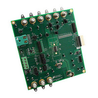
EVAL BOARD FOR LMP90100
Manufacturer
National Semiconductor
Datasheet
1.LMP90100EBNOPB.pdf
(30 pages)
Specifications of LMP90100EB/NOPB
Main Purpose
Interface, Analog Front End (AFE)
Embedded
No
Utilized Ic / Part
LMP90100
Primary Attributes
8 Programmable Output Data Rates Per Channel
Secondary Attributes
SPI Interface
Silicon Manufacturer
National
Silicon Core Number
LMP90100
Kit Application Type
Data Converter
Application Sub Type
ADC
Kit Contents
LMP90100 Evaluation Board
Lead Free Status / RoHS Status
Lead free / RoHS Compliant


5.0. Example #3 - 3-wire RTD Application
© 2009 National Semiconductor Corporation
A 3-wire RTD has a typical configuration shown in Figure 11. This section will explain how to configure the
LMP90100EB and software tool to evaluate a 3-wire RTD.
A. LMP90100EB Jumper Connections
1.
2.
3.
Jumper
JP11
JP1
JP2
JP4
JP6
JP7
Figure 20
The jumpers not mentioned in this table have to be left unconnected for this exercise.
SPIO-4 board is properly setup out of the box (no assembly required).
shows the schematic.
RTD from Omega
P/N: PRTF-10-2-100-1/4-6-E
WHITE
RED
RED
PT-100
RTD
Figure 11 - 3-Wire RTD Configuration
RLINE1
RLINE2
RLINE3
Jumper Connections
RREF = 1 kOhm
Pins 2 & 3
Pins 2 & 3
Pins 1 & 2
Pins 1 & 2
Pins 1 & 2
Pins 1 & 2
J10
4
1
2
3
Page 13 of 30
= 0 Ohm
RRTD2
with Sensor AFE Software User’s Guide
VIN1
IB2
VIN0
IB1
VIN6 / VREFP2
VIN7 / VREFN2
LMP90100
VA
lmp90100eb_usersguide_20101227_v23.doc
VA
1000 uA
LMP90100 Evaluation Board
VA = SPIO4_PWR
VIO = SPIO4_PWR
SPIO4_PWR = 3.3V
Connect VA to LMP90100
Connect VIO to LMP90100
Connect IB1 to VIN0
1000 uA
Purpose
Related parts for LMP90100EB/NOPB
Image
Part Number
Description
Manufacturer
Datasheet
Request
R

Part Number:
Description:
National Semiconductor [8-Bit D/A Converter]
Manufacturer:
National Semiconductor
Datasheet:
Part Number:
Description:
National Semiconductor [Media Coprocessor]
Manufacturer:
National Semiconductor
Datasheet:
Part Number:
Description:
Digitally Controlled Tone and Volume Circuit with Stereo Audio Power Amplifier, Microphone Preamp Stage and National 3D Sound
Manufacturer:
National Semiconductor
Datasheet:
Part Number:
Description:
Digitally Controlled Tone and Volume Circuit with Stereo Audio Power Amplifier, Microphone Preamp Stage and National 3D Sound
Manufacturer:
National Semiconductor
Datasheet:
Part Number:
Description:
AC97 Rev 2 Codec with Sample Rate Conversion and National 3D Sound
Manufacturer:
National Semiconductor
Part Number:
Description:
Manufacturer:
National Semiconductor
Datasheet:
Part Number:
Description:
Manufacturer:
National Semiconductor
Datasheet:
Part Number:
Description:
General Purpose, Low Voltage, Low Power, Rail-to-Rail Output Operational Amplifiers
Manufacturer:
National Semiconductor
Datasheet:
Part Number:
Description:
8-bit 20 MSPS flash A/D converter.
Manufacturer:
National Semiconductor
Datasheet:
Part Number:
Description:
Low Noise Quad Operational Amplifier
Manufacturer:
National Semiconductor
Datasheet:
Part Number:
Description:
Quad Differential Line Receivers
Manufacturer:
National Semiconductor
Datasheet:
Part Number:
Description:
Quad High Speed Trapezoidal? Bus Transceiver
Manufacturer:
National Semiconductor
Datasheet:
Part Number:
Description:
Dual Line Receiver
Manufacturer:
National Semiconductor
Datasheet:
Part Number:
Description:
TTL to 10k ECL Level Translator with Latch
Manufacturer:
National Semiconductor
Datasheet: