GCM188R71H103KA37D Murata, GCM188R71H103KA37D Datasheet - Page 16
GCM188R71H103KA37D
Manufacturer Part Number
GCM188R71H103KA37D
Description
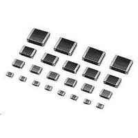
Multilayer Ceramic Capacitors (MLCC) - SMD/SMT 0603 0.01uF 50volts X7R 10%
Manufacturer
Murata
Series
GCMr
Datasheets
1.GCM188R71C105KA64D.pdf
(50 pages)
2.GCM188R71H103KA37D.pdf
(1 pages)
3.GCM155R71C104KA55D.pdf
(2 pages)
Specifications of GCM188R71H103KA37D
Voltage Rating
50 Volts
Operating Temperature Range
- 55 C to + 125 C
Temperature Coefficient / Code
X7R
Product
Automotive MLCCs
Dimensions
0.8 mm W x 1.6 mm L x 0.8 mm H
Termination Style
SMD/SMT
Capacitance
0.01 uF
Tolerance
10 %
Package / Case
0603 (1608 metric)
Lead Free Status / RoHS Status
Lead free / RoHS Compliant
Available stocks
Company
Part Number
Manufacturer
Quantity
Price
Company:

Part Number:
GCM188R71H103KA37D
Manufacturer:
MURATA
Quantity:
640 000
Company:
Part Number:
GCM188R71H103KA37D
Manufacturer:
MURATA
Quantity:
32 000
Part Number:
GCM188R71H103KA37D 0603 X7R 103K 50V
Manufacturer:
MURATA/村田
Quantity:
20 000


1
!Note
• This PDF catalog is downloaded from the website of Murata Manufacturing co., ltd. Therefore, it’s specifications are subject to change or our products in it may be discontinued without advance notice. Please check with our
• This PDF catalog has only typical specifications because there is no space for detailed specifications. Therefore, please approve our product specifications or transact the approval sheet for product specifications before ordering.
sales representatives or product engineers before ordering.
!Note
14
No.
10
11
12 Vibration
13
Specifications and Test Methods
7
8
9
Continued from the preceding page.
Operational Life
External Visual
Physical Dimension
Resistance
to Solvents
Mechanical
Shock
Resistance to
Soldering Heat
• Please read rating and !CAUTION (for storage, operating, rating, soldering, mounting and handling) in this catalog to prevent smoking and/or burning, etc.
• This catalog has only typical specifications because there is no space for detailed specifications. Therefore, please approve our product specifications or transact the approval sheet for product specifications before ordering.
AEC-Q200
Test Item
Appearance
Capacitance
Change
Q/D.F.
I.R.
Appearance
Capacitance
Change
Q/D.F.
I.R.
Appearance
Capacitance
Change
Q/D.F.
I.R.
Appearance
Capacitance
Change
Q/D.F.
I.R.
Appearance
Capacitance
Change
Q/D.F.
I.R.
Temperature Compensating Type
The measured and observed characteristics should satisfy the
specifications in the following table.
No marking defects
Within ±3.0% or ±0.30pF
(Whichever is larger)
30pFmin.: QU350
10pF and over, 30pF and below:
QU275+
10pFmax.: QU200+10C
C: Nominal Capacitance (pF)
More than 1,000MΩ or 50Ω · F
(Whichever is smaller)
No defects or abnormalities
Within the specified dimensions
No marking defects
Within the specified tolerance
30pFmin.: QU1000
30pFmax.: QU400+20C
C: Nominal Capacitance (pF)
More than 10,000MΩ or 500Ω · F
(Whichever is smaller)
No marking defects
Within the specified tolerance
30pFmin.: QU1000
30pFmax.: QU400+20C
C: Nominal Capacitance (pF)
More than 10,000MΩ or 500Ω · F
(Whichever is smaller)
No defects or abnormalities
Within the specified tolerance
30pFmin.: QU1000
30pFmax.: QU400+20C
C: Nominal Capacitance (pF)
More than 10,000MΩ or 500Ω · F
(Whichever is smaller)
The measured and observed characteristics should satisfy the
specifications in the following table.
No marking defects
Within the specified tolerance
30pFmin.: QU1000
30pFmax.: QU400+20C
C: Nominal Capacitance (pF)
More than 10,000MΩ or 500Ω · F
(Whichever is smaller)
Y
5
2
C
Specifications
Within ±12.5%
W.V.: 25Vmin.: 0.035 max.
W.V.: 16V: 0.05 max.
W.V.: 25Vmin.: 0.025 max.
W.V.: 16V: 0.035 max.
W.V.: 25Vmin.: 0.025 max.
W.V.: 16V: 0.035 max.
W.V.: 25Vmin.: 0.025 max.
W.V.: 16V: 0.035 max.
W.V.: 25Vmin.: 0.025 max.
W.V.: 16V: 0.035 max.
High Dielectric Type
GCM Series Specification and Test Methods
*1
*1
*1
*1
*1
*1
*1
*1
*1
*1
Apply 200% of the rated voltage for 1000±12 hours at
125±3°C. Let sit for 24±2 hours at room temperature, then
measure. *2
The charge/discharge current is less than 50mA.
• Initial measurement for high dielectric constant type.
Apply 200% of the rated DC voltage for one hour at the maximum
operating temperature ±3°C. Remove and let sit for 24±2 hours
at room temperature. Perform initial measurement. *2
Visual inspection
Using calipers
Per MIL-STD-202 Method 215
Three shocks in each direction should be applied along 3
mutually perpendicular axes of the test specimen (18 shocks).
The specified test pulse should be Half-sine and should have a
duration: 0.5ms, peak value: 1500g and velocity change: 4.7m/s.
Solder the capacitor to the test jig (glass epoxy board) in the
same manner and under the same conditions as (19). The
capacitor should be subjected to a simple harmonic motion
having a total amplitude of 1.5mm, the frequency being varied
uniformly between the approximate limits of 10 and 2000Hz. The
frequency range, from 10 to 2000Hz and return to 10Hz, should
be traversed in approximately 20 minutes. This motion should be
applied for 12 items in each 3 mutually perpendicular directions
(total of 36 times).
Immerse the capacitor in a eutectic solder solution at 260±5°C for
10±1 seconds. Let sit at room temperature for 24±2 hours, then
measure.
• Initial measurement for high dielectric constant type
Perform a heat treatment at 150
sit for 24±2 hours at room temperature.
Perform the initial measurement.
Solvent 1: 1 part (by volume) of isopropyl alcohol
Solvent 2: Terpene defluxer
Solvent 3: 42 parts (by volume) of water
3 parts (by volume) of mineral spirits
1 part (by volume) of propylene glycol
monomethyl ether
1 part (by volume) of monoethanolamine
AEC-Q200 Test Method
Continued on the following page.
W0
Y10
°C for one hour and then let
C03E.pdf
09.3.31
Related parts for GCM188R71H103KA37D
Image
Part Number
Description
Manufacturer
Datasheet
Request
R

Part Number:
Description:
Murata Microblower 20x20 DCDC Driver Board - Samples Only
Manufacturer:
Murata
Part Number:
Description:
357-036-542-201 CARDEDGE 36POS DL .156 BLK LOPRO
Manufacturer:
Murata
Datasheet:
Part Number:
Description:
Manufacturer:
Murata
Datasheet:
Part Number:
Description:
Manufacturer:
Murata
Datasheet:
Part Number:
Description:
Manufacturer:
Murata
Datasheet:
Part Number:
Description:
Manufacturer:
Murata
Datasheet:
Part Number:
Description:
Manufacturer:
Murata
Datasheet:
Part Number:
Description:
Manufacturer:
Murata
Datasheet:
Part Number:
Description:
Manufacturer:
Murata
Datasheet:
Part Number:
Description:
BLM21BD751SN1On-Board Type (DC) EMI Suppression Filters
Manufacturer:
Murata
Datasheet:
Part Number:
Description:
BLM15AG100SN1On-Board Type (DC) EMI Suppression Filters
Manufacturer:
Murata
Datasheet:
Part Number:
Description:
NFE31PT222Z1E9On-Board Type (DC) EMI Suppression Filters
Manufacturer:
Murata
Datasheet:
Part Number:
Description:
Chip Coil
Manufacturer:
Murata
Datasheet:
Part Number:
Description:
Chip Coil
Manufacturer:
Murata
Datasheet: