GCM188R71H103KA37D Murata, GCM188R71H103KA37D Datasheet - Page 27
GCM188R71H103KA37D
Manufacturer Part Number
GCM188R71H103KA37D
Description
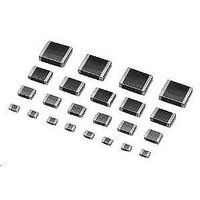
Multilayer Ceramic Capacitors (MLCC) - SMD/SMT 0603 0.01uF 50volts X7R 10%
Manufacturer
Murata
Series
GCMr
Datasheets
1.GCM188R71C105KA64D.pdf
(50 pages)
2.GCM188R71H103KA37D.pdf
(1 pages)
3.GCM155R71C104KA55D.pdf
(2 pages)
Specifications of GCM188R71H103KA37D
Voltage Rating
50 Volts
Operating Temperature Range
- 55 C to + 125 C
Temperature Coefficient / Code
X7R
Product
Automotive MLCCs
Dimensions
0.8 mm W x 1.6 mm L x 0.8 mm H
Termination Style
SMD/SMT
Capacitance
0.01 uF
Tolerance
10 %
Package / Case
0603 (1608 metric)
Lead Free Status / RoHS Status
Lead free / RoHS Compliant
Available stocks
Company
Part Number
Manufacturer
Quantity
Price
Company:

Part Number:
GCM188R71H103KA37D
Manufacturer:
MURATA
Quantity:
640 000
Company:
Part Number:
GCM188R71H103KA37D
Manufacturer:
MURATA
Quantity:
32 000
Part Number:
GCM188R71H103KA37D 0603 X7R 103K 50V
Manufacturer:
MURATA/村田
Quantity:
20 000


!Note
• This PDF catalog is downloaded from the website of Murata Manufacturing co., ltd. Therefore, it’s specifications are subject to change or our products in it may be discontinued without advance notice. Please check with our
• This PDF catalog has only typical specifications because there is no space for detailed specifications. Therefore, please approve our product specifications or transact the approval sheet for product specifications before ordering.
sales representatives or product engineers before ordering.
!Note
6. Correction with a Soldering Iron
(1) For Chip Type Capacitors
7. Washing
FAILURE TO FOLLOW THE ABOVE CAUTIONS MAY
RESULT, WORST CASE, IN A SHORT CIRCUIT AND
FUMING WHEN THE PRODUCTS IS USED.
!Caution
Optimum Solder Amount when re-working Using a
Please carry it out after having confirmed that there is not
Excessive output of ultrasonic oscillation during cleaning
chips or broken solder. Take note not to vibrate PCBs.
When sudden heat is applied to the components by use
of a soldering iron, the mechanical strength of the
components will go down because the extreme
temperature change causes deformations inside the
components. In order to prevent mechanical damage to
the components, preheating is required for both the
Soldering Iron
In case of smaller size than 0603, (GCM03/15/18), the
top of the solder fillet should be lower than 2/3's of the
thickness of the component or 0.5mm whichever is
smaller. In case of 0805 and larger sizes,
(GCM21/31/32), the top of the solder fillet should be
lower than 2/3's of the thickness of the components. If
the solder amount is excessive, the risk of cracking is
abnormality such as product cracks by mounter beforehand.
components and the PCB board. Preheating conditions,
(The "Temperature of the Soldering Iron tip", "Preheating
Temperature", "Temperature Differential" between the
iron tip and the components and the PCB), should be
within the conditions of table 3. It is required to keep the
temperature differential between the soldering Iron and
the components surface ( T) as small as possible. After
soldering, do not allow the component/PCB to cool down
rapidly. The operating time for the re-working should be
as short as possible. When re-working time is too long, it
may cause solder leaching, and that will cause a
reduction of the adhesive strength of the terminations.
higher during board bending or under any other stressful
conditions. A Soldering iron ø3mm or smaller should be
used. It is also necessary to keep the soldering iron from
touching the components during the re-work. Solder wire
with ø0.5mm or smaller is required for soldering.
causes PCBs to resonate, resulting in cracked
Continued from the preceding page.
• Please read rating and !CAUTION (for storage, operating, rating, soldering, mounting and handling) in this catalog to prevent smoking and/or burning, etc.
• This catalog has only typical specifications because there is no space for detailed specifications. Therefore, please approve our product specifications or transact the approval sheet for product specifications before ordering.
Table 3
GCM03/15/18/21/31 350 C max.
GCM32
*Applicable for both Pb-Sn and Lead Free Solder.
Pb-Sn Solder: Sn-37Pb
Lead Free Solder: Sn-3.0Ag-0.5Cu
Part Number
280 C max.
Temperature
of Soldering
Iron tip
Temperature
150 C min.
150 C min.
Preheating
Temperature
Differential
TV190 C
TV130 C
!Caution
( T)
Solder Amount
Atomosphere
in section
Air
Air
C03E.pdf
25
09.3.31
1
Related parts for GCM188R71H103KA37D
Image
Part Number
Description
Manufacturer
Datasheet
Request
R

Part Number:
Description:
Murata Microblower 20x20 DCDC Driver Board - Samples Only
Manufacturer:
Murata
Part Number:
Description:
357-036-542-201 CARDEDGE 36POS DL .156 BLK LOPRO
Manufacturer:
Murata
Datasheet:
Part Number:
Description:
Manufacturer:
Murata
Datasheet:
Part Number:
Description:
Manufacturer:
Murata
Datasheet:
Part Number:
Description:
Manufacturer:
Murata
Datasheet:
Part Number:
Description:
Manufacturer:
Murata
Datasheet:
Part Number:
Description:
Manufacturer:
Murata
Datasheet:
Part Number:
Description:
Manufacturer:
Murata
Datasheet:
Part Number:
Description:
Manufacturer:
Murata
Datasheet:
Part Number:
Description:
BLM21BD751SN1On-Board Type (DC) EMI Suppression Filters
Manufacturer:
Murata
Datasheet:
Part Number:
Description:
BLM15AG100SN1On-Board Type (DC) EMI Suppression Filters
Manufacturer:
Murata
Datasheet:
Part Number:
Description:
NFE31PT222Z1E9On-Board Type (DC) EMI Suppression Filters
Manufacturer:
Murata
Datasheet:
Part Number:
Description:
Chip Coil
Manufacturer:
Murata
Datasheet:
Part Number:
Description:
Chip Coil
Manufacturer:
Murata
Datasheet: