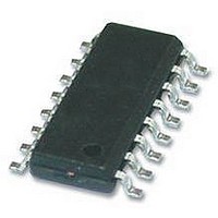
DS90LV031ATM National Semiconductor, DS90LV031ATM Datasheet - Page 7

DS90LV031ATM
Manufacturer Part Number
DS90LV031ATM
Description
IC, LVDS DIFFERENTIAL LINE DRIVER SOIC16
Manufacturer
National Semiconductor
Datasheet
1.DS90LV031ATM.pdf
(10 pages)
Specifications of DS90LV031ATM
Supply Current
30mA
Supply Voltage Range
3V To 3.6V
Driver Case Style
SOIC
No. Of Pins
16
Operating Temperature Range
-40°C To +85°C
Device Type
Differential Line Receiver
Esd Hbm
6kV
Rohs Compliant
No
Lead Free Status / RoHS Status
Contains lead / RoHS non-compliant
Available stocks
Company
Part Number
Manufacturer
Quantity
Price
Company:
Part Number:
DS90LV031ATM
Manufacturer:
NS
Quantity:
60
Company:
Part Number:
DS90LV031ATM
Manufacturer:
IR
Quantity:
75
Part Number:
DS90LV031ATM
Manufacturer:
NS/国半
Quantity:
20 000
Company:
Part Number:
DS90LV031ATM/NOPB
Manufacturer:
TI
Quantity:
446
Company:
Part Number:
DS90LV031ATMTC
Manufacturer:
NS
Quantity:
8
Part Number:
DS90LV031ATMTCX
Manufacturer:
TI/德州仪器
Quantity:
20 000
Part Number:
DS90LV031ATMTCX/NOPB
Manufacturer:
NS/国半
Quantity:
20 000
Part Number:
DS90LV031ATMX
Manufacturer:
TI/德州仪器
Quantity:
20 000
Company:
Part Number:
DS90LV031ATMX/NOPB
Manufacturer:
NS
Quantity:
5 214
Part Number:
DS90LV031ATMX/NOPB
Manufacturer:
NS/国半
Quantity:
20 000
Probing LVDS Transmission Lines:
Always use high impedance (> 100kΩ), low capacitance
(< 2pF) scope probes with a wide bandwidth (1GHz) scope.
Improper probing will give deceiving results.
Cables and Connectors, General Comments:
When choosing cable and connectors for LVDS it is important
to remember:
Use controlled impedance media. The cables and connectors
you use should have a matched differential impedance of
about 100Ω. They should not introduce major impedance dis-
continuities.
Balanced cables (e.g. twisted pair) are usually better than
unbalanced cables (ribbon cable, simple coax.) for noise re-
duction and signal quality. Balanced cables tend to generate
less EMI due to field canceling effects and also tend to pick
up electromagnetic radiation as common-mode (not differen-
Typical Application
FIGURE 7. Point-to-Point Application
FIGURE 6. Driver Output Levels
7
tial mode) noise which is rejected by the receiver. For cable
distances < 0.5M, most cables can be made to work effec-
tively. For distances 0.5M
twisted pair cable works well, is readily available and relatively
inexpensive.
Fail-safe of an LVDS Interface
If the LVDS link as shown in
case where the Line Driver is disabled, powered off, or re-
moved (un-plugged) and the Receiver device is powered on
and enabled, the state of the LVDS bus is unknown and
therefore the output state of the Receiver is also unknown. If
this is of concern, please consult the respective LVDS Re-
ceiver data sheet for guidance on Failafe Biasing options for
the LVDS interface to set a known state on the inputs for these
conditions.
≤
d
Figure 7
≤
10M, CAT 3 (category 3)
10009508
needs to support the
10009509
www.national.com


