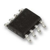
LM3404MA National Semiconductor, LM3404MA Datasheet - Page 15

LM3404MA
Manufacturer Part Number
LM3404MA
Description
DRIVER, LED, 1A, POWERWISE, SO-8, 3404
Manufacturer
National Semiconductor
Datasheet
1.LM3404MA.pdf
(28 pages)
Specifications of LM3404MA
Led Driver Application
Automotive, Industrial Lighting
No. Of Outputs
1
Output Current
1.2A
Output Voltage
40V
Input Voltage
6V To 42V
Dimming Control Type
PWM
Operating
RoHS Compliant
Topology
Buck
Available stocks
Company
Part Number
Manufacturer
Quantity
Price
Part Number:
LM3404MAX
Manufacturer:
NS/国半
Quantity:
20 000
Part Number:
LM3404MAX/NOPB
Manufacturer:
NS/国半
Quantity:
20 000
creasing at higher temperatures. Consequently, with a maxi-
mum Vcc voltage of 7.4V, current will be observed in the LEDs
if the total stack voltage is less than about 6V at a forward
current of several microamps. No current is observed if the
stack voltage is above 6V, as shown in . The need for absolute
darkness during DIM mode is also application dependent. It
will not affect regular PWM dimming operation.
The fix for this issue is extremely simple. Place a resistor from
the SW pin to ground according to the chart below.
The luminaire designer should ensure that the suggested re-
sistor is effective in eliminating the off-state light output. A
combination of calculations based on LED manufacturer data
and lab measurements over temperature will ensure the best
design.
Transient Protection
Considerations
Considerations need to be made when external sources,
loads or connections are made to the switching converter cir-
cuit due to the possibility of Electrostatic Discharge (ESD) or
Electric Over Stress (EOS) events occurring and damaging
the integrated circuit (IC) device. All IC device pins contain
zener based clamping structures that are meant to clamp
ESD. ESD events are very low energy events, typically less
Number of LEDs
>5
1
2
3
4
5
Resistor Value (kΩ)
150
200
300
20
50
90
FIGURE 6. CS Pin, Transient Path
15
than 5µJ (microjoules). Any event that transfers more energy
than this may damage the ESD structure. Damage is typically
represented as a short from the pin to ground as the extreme
localized heat of the ESD / EOS event causes the aluminum
metal on the chip to melt, causing the short. This situation is
common to all integrated circuits and not just unique to the
LM340X device.
CS PIN PROTECTION
When hot swapping in a load (e.g. test points, load boards,
LED stack), any residual charge on the load will be immedi-
ately transferred through the output capacitor to the CS pin,
which is then damaged as shown in
event due to the residual charge from the load is represented
as V
From measurements, we know that the 8V ESD structure on
the CS pin can typically withstand 25mA of direct current
(DC). Adding a 1kΩ resistor in series with the CS pin, shown
in
pass through the discrete sense resistor rather than the de-
vice. The series resistor limits the peak current that can flow
during a transient event, thus protecting the CS pin. With the
1kΩ resistor shown, a 33V, 49A transient on the LED return
connector terminal could be absorbed as calculated by:
This is an extremely high energy event, so the protection
measures previously described should be adequate to solve
this issue.
Figure
TRANSIENT
7, results in the majority of the transient energy to
.
V = 25mA * 1kΩ + 8V = 33V
I = 33V / 0.67Ω = 49A
Figure 6
20205463
below. The EOS
www.national.com


