LM2679T-5.0 National Semiconductor, LM2679T-5.0 Datasheet - Page 5
LM2679T-5.0
Manufacturer Part Number
LM2679T-5.0
Description
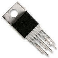
IC, STEP-DOWN REGULATOR, TO-220-7
Manufacturer
National Semiconductor
Datasheet
1.LM2679S-3.3.pdf
(26 pages)
Specifications of LM2679T-5.0
Primary Input Voltage
12V
No. Of Outputs
1
Output Voltage
5V
Output Current
5A
No. Of Pins
7
Operating Temperature Range
-40°C To +125°C
Supply Voltage Range
8V To 40V
Lead Free Status / RoHS Status
Contains lead / RoHS non-compliant
Available stocks
Company
Part Number
Manufacturer
Quantity
Price

Part Number:
LM2679T-5.0/NOPB
Manufacturer:
NS/国半
Quantity:
20 000


Note 1: Absolute Maximum Ratings are limits beyond which damage to the device may occur. Operating Ratings indicate conditions under which of the device
is guaranteed. Operating Ratings do not imply guaranteed performance limits. For guaranteed performance limits and associated test condition, see the electrical
Characteristics tables.
Note 2: ESD was applied using the human-body model, a 100pF capacitor discharged through a 1.5 kΩ resistor into each pin.
Note 3: Typical values are determined with T
= T
= 25°C and represent the most likely norm.
A
J
Note 4: All limits are guaranteed at room temperature (standard type face) and at temperature extremes (bold type face). All room temperature limits are 100%
tested during production with T
= T
= 25°C. All limits at temperature extremes are guaranteed via correlation using standard standard Quality Control (SQC)
A
J
methods. All limits are used to calculate Average Outgoing Quality Level (AOQL).
Note 5: The peak switch current limit is determined by the following relationship: I
=37,125/ R
.
CL
ADJ
Note 6: Junction to ambient thermal resistance (no external heat sink) for the 7 lead TO-220 package mounted vertically, with ½ inch leads in a socket, or on a
PC board with minimum copper area.
Note 7: Junction to ambient thermal resistance (no external heat sink) for the 7 lead TO-220 package mounted vertically, with ½ inch leads soldered to a PC
board containing approximately 4 square inches of (1 oz.) copper area surrounding the leads.
Note 8: Junction to ambient thermal resistance for the 7 lead TO-263 mounted horizontally against a PC board area of 0.136 square inches (the same size as
the TO-263 package) of 1 oz. (0.0014 in. thick) copper.
Note 9: Junction to ambient thermal resistance for the 7 lead TO-263 mounted horizontally against a PC board area of 0.4896 square inches (3.6 times the area
of the TO-263 package) of 1 oz. (0.0014 in. thick) copper.
Note 10: Junction to ambient thermal resistance for the 7 lead TO-263 mounted horizontally against a PC board copper area of 1.0064 square inches (7.4 times
the area of the TO-263 package) of 1 oz. (0.0014 in. thick) copper. Additional copper area will reduce thermal resistance further. See the thermal model in Switchers
Made Simple
®
software.
Note 11: Junction to ambient thermal resistance for the 14-lead LLP mounted on a PC board copper area equal to the die attach paddle.
Note 12: Junction to ambient thermal resistance for the 14-lead LLP mounted on a PC board copper area using 12 vias to a second layer of copper equal to die
attach paddle. Additional copper area will reduce thermal resistance further. For layout recommendations, refer to Application Note AN-1187.
Note 13: The absolute maximum specification of the 'Switch Voltage to Ground' applies to DC voltage. An extended negative voltage limit of -10V applies to a
pulse of up to 20 ns, -6V of 60 ns and -3V of up to 100 ns.
5
www.national.com
Related parts for LM2679T-5.0
Image
Part Number
Description
Manufacturer
Datasheet
Request
R

Part Number:
Description:
IC REG SIMPLE SWITCHER TO-220-7
Manufacturer:
National Semiconductor
Datasheet:
Part Number:
Description:
IC REG SIMPLE SWITCHER TO-220-7
Manufacturer:
National Semiconductor
Datasheet:

Part Number:
Description:
IC, STEP-DOWN REGULATOR, TO-220-7
Manufacturer:
National Semiconductor
Datasheet:
Part Number:
Description:
Power Supply IC
Manufacturer:
National Semiconductor
Datasheet:
Part Number:
Description:
DC/DC Converter IC
Manufacturer:
National Semiconductor
Datasheet:
Part Number:
Description:
IC REG SIMPLE SWITCHER TO-220-7
Manufacturer:
National Semiconductor
Datasheet:
Part Number:
Description:
IC REG SIMPLE SWITCHER TO-220-7
Manufacturer:
National Semiconductor
Datasheet:

Part Number:
Description:
EVALUATION BOARD FOR LM2679-5.0
Manufacturer:
National Semiconductor
Datasheet:

Part Number:
Description:
National Semiconductor [8-Bit D/A Converter]
Manufacturer:
National Semiconductor
Datasheet:
Part Number:
Description:
National Semiconductor [Media Coprocessor]
Manufacturer:
National Semiconductor
Datasheet:
Part Number:
Description:
Digitally Controlled Tone and Volume Circuit with Stereo Audio Power Amplifier, Microphone Preamp Stage and National 3D Sound
Manufacturer:
National Semiconductor
Datasheet:
Part Number:
Description:
Digitally Controlled Tone and Volume Circuit with Stereo Audio Power Amplifier, Microphone Preamp Stage and National 3D Sound
Manufacturer:
National Semiconductor
Datasheet:
Part Number:
Description:
AC97 Rev 2 Codec with Sample Rate Conversion and National 3D Sound
Manufacturer:
National Semiconductor
Part Number:
Description:
Manufacturer:
National Semiconductor
Datasheet: