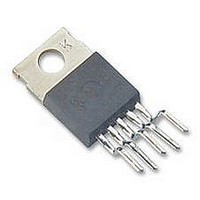
LM2591HVT-3.3 National Semiconductor, LM2591HVT-3.3 Datasheet - Page 8

LM2591HVT-3.3
Manufacturer Part Number
LM2591HVT-3.3
Description
Voltage Regulator IC
Manufacturer
National Semiconductor
Specifications of LM2591HVT-3.3
Output Voltage
3.3VDC
Output Current
1A
No. Of Pins
5
Termination Type
Through Hole
Mounting Type
Through Hole
Peak Reflow Compatible (260 C)
No
Supply Voltage Max
60V
Leaded Process Compatible
No
Lead Free Status / RoHS Status
Contains lead / RoHS non-compliant
www.national.com
Test Circuit and Layout Guidelines
Component Values shown are for V
V
C
C
D1
L1
Select R
Component Values shown are for V
V
C
C
D1 — 2A, 60V Schottky Rectifier, 21DQ06 (International Rectifier)
L1 — 100 µH, See Inductor Selection Procedure
R
R
C
Typical Values
C
C
R
drag feedback pin below ground). Required if V
†
OUT
IN
OUT
OUT
IN
OUT
1
2
FF
SS
DELAY
PULL UP
Small signal Schottky diode to prevent damage to feedback pin by negative spike when output is shorted (C
:
— 1 kΩ, 1%
— 7.15k, 1%
— 0.1 µF
— 3.3 nF
—
:
—
= 5V, I
—
= 10V, I
— 470 µF, 35V, Aluminum Electrolytic Nichicon “PM Series”
— 0.1 µF
—
1
— 220 µF, 35V Aluminum Electrolytic, Nichicon “PM Series”
68 µH, See Inductor Selection Procedure
2A, 60V Schottky Rectifier, 21DQ06 (International Rectifier)
to be approximately 1 kΩ, use a 1% resistor for best stability.
— 4.7k (use 22k if V
470 µF, 50V, Aluminum Electrolytic Nichicon “PM Series”
LOAD
220 µF, 25V Aluminum Electrolytic, Nichicon “PM Series”
LOAD
= 1A.
= 1A.
OUT
IN
IN
is ≥ 45V)
= 15V,
= 20V,
FIGURE 1. Standard Test Circuits and Layout Guides
IN
>
40V
Adjustable Output Voltage Versions
Fixed Output Voltage Versions
8
FF
not being able to discharge immediately will
10129325
10129324


