G6KU-2PY 3DC Omron, G6KU-2PY 3DC Datasheet - Page 9
G6KU-2PY 3DC
Manufacturer Part Number
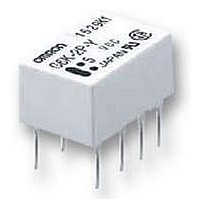
G6KU-2PY 3DC
Description
RELAY, PCB, SPCO, 3VDC, LATCHING
Manufacturer
Omron
Datasheet
1.G6KU-2FY_3DC.pdf
(10 pages)
Specifications of G6KU-2PY 3DC
Contact Current Max
1A
Contact Voltage Ac Nom
125V
Contact Voltage Dc Nom
30V
Coil Voltage Vdc Nom
3V
Coil Resistance
91ohm
Coil Power Cont
100mW
Relay
RoHS Compliant
Coil Type
DC Coil
Coil Current
33mA
Contact Configuration
DPDT
Rohs Compliant
Yes


G6K
Recommended Soldering Method
Temperature indicate the surface temperature of the PCBs.
IRS Method (for surface mounting terminal models)
(1) IRS Method (Mounting Solder: Lead)
• The thickness of cream solder to be applied should be within a range between 150 and 200 µm on OMRON’s recommended PCB pattern.
• In order to perform correct soldering, it is recommended that the correct soldering conditions be maintained as shown below on the left
Visually check that the Relay is properly soldered.
■
UL approval:UL1950 (File No. E41515)
CSA approval:C22.2 No. 950 (File No. LR31928)
DPDT
side.
PCB
Correct Soldering
Approved Standards
220 to
180 to
Contact form
245
200
150
Terminal
Relay
Solder
Preheating
Land
90 to 120
G6K-2G(F/P): 3 to 12 VDC
G6K(U)-2G(F/P)-Y: 3 to 24 VDC
Incorrect Soldering
Soldering
20 to 30
Coil rating
Insufficient
amount of
solder
Time (s)
1 A at 30 VDC
0.5 A at 60 VDC
0.3 A at 125 VAC
Excessive
amount of
solder
Contact rating
(2) IRS Method (Mounting Solder: Lead-free)
Note: The temperature profile indicates the
250 max.
230
180
150
temperature of the relay terminal
section.
Upper surface of case (peak):
255˚C max.
120 max.
Preheating
6,000
Number of test operations
30 max.
Soldering
Relay
terminal
section
Time (s)
G6K
99
Related parts for G6KU-2PY 3DC
Image
Part Number
Description
Manufacturer
Datasheet
Request
R

Part Number:
Description:
RELAY, PCB, SPCO, 5VDC, LATCHING
Manufacturer:
Omron
Datasheet:

Part Number:
Description:
RELAY LOW SIGNAL PCB
Manufacturer:
Omron
Datasheet:

Part Number:
Description:
RELAY LOW SIGNAL PCB
Manufacturer:
Omron
Datasheet:
Part Number:
Description:
LOW SIGNAL RELAY
Manufacturer:
Omron
Datasheet:
Part Number:
Description:
Low Signal Relay
Manufacturer:
Omron
Datasheet:
Part Number:
Description:
LOW SIGNAL RELAY
Manufacturer:
Omron
Datasheet:

Part Number:
Description:
SURFACE MOUNT RELAY
Manufacturer:
Omron
Datasheet:
Part Number:
Description:
SURFACE MOUNT RELAY
Manufacturer:
Omron
Datasheet:
Part Number:
Description:
SURFACE MOUNT RELAY
Manufacturer:
Omron
Datasheet:
Part Number:
Description:
SURFACE MOUNT RELAY
Manufacturer:
Omron
Datasheet: