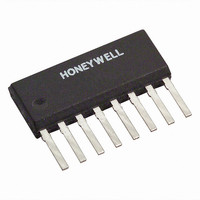
HMC1001 Honeywell Microelectronics & Precision Sensors, HMC1001 Datasheet - Page 11

HMC1001
Manufacturer Part Number
HMC1001
Description
SENSOR LINEAR MAGN 1 AXIS 8-SIP
Manufacturer
Honeywell Microelectronics & Precision Sensors
Type
Linearr
Datasheet
1.HMC1021S.pdf
(15 pages)
Specifications of HMC1001
Rohs Status
RoHS non-compliant
Sensing Range
±2g
Voltage - Supply
5 V ~ 12 V
Output Type
Differential Voltage
Features
Compass - One Axis
Operating Temperature
-55°C ~ 150°C
Package / Case
8 Pin SIP
Current - Supply
-
Current - Output (max)
-
Other names
342-1001-5
Available stocks
Company
Part Number
Manufacturer
Quantity
Price
Company:
Part Number:
HMC1001
Manufacturer:
SILICON
Quantity:
6 934
Company:
Part Number:
HMC1001RC
Manufacturer:
HONEYWELL
Quantity:
5 000
HMC1001/1002/1021/1022
APPLICATION CIRCUITS
The following are typical application circuits using the HMC100x and HMC102x sensors.
TWO AXIS COMPASS OR MAGNETOMETER
Figure 5 shows the typical schematic diagram.
From Figure 5, the typical power supplied for VDD is nominally 5 volts, with about 8 volts for the set/reset strap supply
(VSR). A pair of complementary power MOSFETs provides the electronic switch functions, driving the set/reset minus
pins with the set/reset plus pins returned to the MOSFET ground. The MOSFETs are driven by typical 5 volt logic with
normally high levels expected when not pulsing. Each logic transition creates a very high current pulse, as high-to-low
transitions turn-on the P-channel FET while turning-off the N-channel FET. This transfers some of the energy from the
10uf reservoir capacitor to the pair of 0.47uf capacitors while providing a positive pulse. A negative pulse is performed on
the low-to-high logic transition as the P-channel FET is turned off and the N-channel FET is turned on. Then the energy
from the pair of 0.47uf capacitors is discharged through the set/reset straps and the N -channel MOSFET. Ceramic
capacitors with a low-ESR characteristic are required for best pulse performance.
Since the sensor output difference voltage is amplified by low cost operational amplifiers with a low supply voltage feature
(LMV324N), the amplifier requires a half supply voltage reference (VREF). This reference voltage is formed via a buffered
rail-splitter circuit, using a spare op-amp and resistors. The 1 nano-farad capacitors are used to bandwidth limit the
sensor, and to suppress interference. The resistors around the op-amp are chosen for earth’s magnetic field strength
(about 0.6 gauss) levels and to match with the sensor impedance. The 4.99k-ohm resistors are a bridging impedance that
is normally chosen to be 4 to 10 times larger than the sensor bridge resistance elements (HMC1002) at 850 ohms. The
www.honeywell.com
1
1
8
8
R1
R1
850
850
R3
R3
850
850
R9
R9
850
850
R11
R11
850
850
HMC1002
HMC1002
R17
R17
1.5
1.5
R18
R18
1.5
1.5
2
2
9
9
VDD
VDD
VDD
VDD
R2
R2
850
850
R4
R4
850
850
R10
R10
850
850
R12
R12
850
850
16
16
R5
R5
4.99K
4.99K
R6
R6
4.99K
4.99K
R13
R13
4.99K
4.99K
R14
R14
4.99K
4.99K
Figure 5 – 2-Axis Compass or Magnetometer
VREF
VREF
VREF
VREF
3
3
4
4
11
11
10
10
R8
R8
360K
360K
R16
R16
360K
360K
C1
C1
1N
1N
C2
C2
1N
1N
C6
C6
0.47U
0.47U
C5
C5
0.47U
0.47U
VCC
VCC
VCC
VCC
VEE
VEE
VEE
VEE
R7
R7
360K
360K
R15
R15
360K
360K
VDD
VDD
VDD
VDD
X2
X2
IRF7105P
IRF7105P
X3
X3
IRF7105N
IRF7105N
X1A
X1A
LMV324N
LMV324N
X1B
X1B
LMV324N
LMV324N
C4
C4
10U
10U
6
6
12
12
14
14
17
17
R21
R21
100
100
R19
R19
1K
1K
YOUT
YOUT
R20
R20
1K
1K
XOUT
XOUT
18
18
VDD
VDD
13
13
SR_IN
SR_IN
15
15
VSR
VSR
VDD
VDD
VCC
VCC
VEE
VEE
X1C
X1C
LMV324N
LMV324N
C3
C3
0.1U
0.1U
VREF
VREF
11


