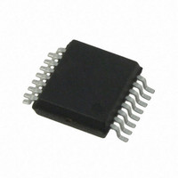
AS5046-ASST austriamicrosystems, AS5046-ASST Datasheet - Page 19

AS5046-ASST
Manufacturer Part Number
AS5046-ASST
Description
IC ENCODER PROG 12-BIT 16-SSOP
Manufacturer
austriamicrosystems
Type
Linear, Rotary Encoder - Programmabler
Datasheet
1.AS5046_PB.pdf
(42 pages)
Specifications of AS5046-ASST
Sensing Range
45mT ~ 75mT
Voltage - Supply
3 V ~ 3.6 V, 4.5 V ~ 5.5 V
Current - Supply
21mA
Current - Output (max)
4mA
Output Type
Analog, Ratiometric
Features
Programmable
Operating Temperature
-40°C ~ 125°C
Package / Case
16-SSOP
Lead Free Status / RoHS Status
Lead free / RoHS Compliant
Other names
AS5046-ASSTTR
AS5046
Data Sheet
Table 18 Example: Differential Measurement of two Opposite Hall Sensors (#1 and 5)
11.4 Analog-Digital Converter Outputs, SIN/COS Signal Bus (Type ID: 0100)
The analog signals on the SIN- and COS- buses are converted into a signed 12-bit digital value by two ADC’s, one for
each bus.
To read the signal from one or more Hall Sensors, first assign a signal bus (SIN, COS) for each Hall Sensor in the
Hall Sensor front-end and then read the corresponding amplitude value from the ADC output register.
Note that the ADC’s are 14-bit (see block diagram,
Figure 2), but only 12-bit are available to the user. The available 12-bit ADC output is again split into an upper 8-bit
block (available in bytes 1 & 2) and a lower 4-bit block in byte 3. The resulting 12-bit value is formatted as a signed
12-bit value and has a range from -2048…+2047 (decimal). Bit 11 (MSB) is the sign bit; if this bit is set, the Sin/Cos
value is negative.
11.5 Automatic Gain Control Register (Type ID: 0111)
The Automatic Gain Control is active in the “green” range of the magnetic field, when the magnetic field is within
~35…63mT. If the magnetic field is too low, e.g. when the magnet is too far away from the chip, the AGC register will
be FF
The Automatic Gain control can be disabled by writing a value into this register. It will be enabled by reading from this
register.
The AGC tries to maintain a constant magnitude value of 3F
magnitude value can no longer be maintained ad 3F
11.6 AGC and Magnitude Registers
The AS5046 allows the readout of two additional registers related to magnetic field strength: magnitude and AGC
registers. Figure 9 shows a graphic example of the interrelations of these two registers in respect to the magnetic field
strength of the magnet (all register levels are in decimal format).
At a low magnetic field strength (below level B1 / B2) the magnitude will be <32 and the AGC will be at maximum:
255. The LIN status bit will be set (red range). It is not recommended to operate in this range, although the AS5046
will still produce usable results at very weak magnetic fields.
www.austriamicrosystems.com
FE0
FE1
FE2
FE3
FE4
FE5
FE6
FE7
Addr.000
Type ID:
H
0100
, if the magnetic field is too strong, e.g. when the magnet is too close to the chip, the AGC register will be 00
Type ID: 0111
Addr
000
001
010
011
100
101
110
111
Addr. 000
11
12-bit ADC output: COS signal bus
10
testEN
0
0
0
0
0
0
0
0
9
AGC7
Upper 8 bits
Byte 1
8
SenseEN
0
1
0
0
0
1
0
0
7
AGC6
6
5
AGC5
NC
0
0
0
0
0
0
0
0
4
NC
0
0
0
0
0
0
0
0
11
Revision 1.12
AGC5
12-bit ADC output: SIN signal bus
H
and will also change accordingly (see 11.1.3 and 11.6).
COS_EN
0
1
0
0
0
1
0
0
Byte 1
10
AGC3
9
Upper 8 bits
H
. If the AGC has reached its upper or lower limit, the
Byte 2
8
SIN_EN
0
0
0
0
0
0
0
0
AGC2
7
6
Inv
0
0
0
0
0
1
0
0
AGC1
5
PD
0
0
0
0
0
0
0
0
4
AGC0
3
COS signal bus
Lower 4 bits
2
1
0
Byte 3
3
SIN signal bus
Lower 4 bits
2
19 – 42
1
0
H
.


